Historically, a part was meshed by determining the thickness of the part and then assigning a surface plane through the middle of the thickness.
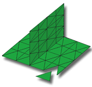
This surface was then meshed with triangular elements that are joined along their edges and corners (called nodes). The thickness of the part is stored in each element. The analysis then incorporates this measurement by dividing the thickness of the part into thin layers called laminae. This provides a defined part volume on which calculations can be performed.
If you want to use a Midplane analysis, ensure the CAD package you use can directly generate a Midplane model. Converting a model into Midplane is a very time-consuming task.
Some results are only available after using Midplane analysis.
In this task, you will:
- Import a Midplane model
- Investigate how the mesh is structured
- Click
 ().
(). - Enter Mesh tutorial for the Project Name .
- Click OK.
- Click
 ().
(). - Select the Files of type drop-down list. The list of file types directly supported is shown. Select Study files (*.sdy) .
- Navigate to the Tutorial folder, typically C:\Program Files\Autodesk\Simulation Moldflow Insight 20xx\tutorial.
- Select dustpan_midplane.sdy then click Open.
- Rotate and zoom in on the model to investigate the part geometry and the way the model has been represented as a Midplane model.
- Note that the Midplane Mesh type and number of elements in the model are displayed in the Study Tasks pane.
Click the Next topic link below to move on to the next task of the tutorial.