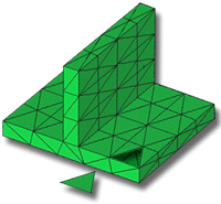
A Dual Domain mesh represents a solid CAD model by covering the surface of the model with triangular elements. The corners of the triangular elements are called nodes.
The model could be visualized as a hollow body covered with a surface shell.
When analyzing a part, the volume of the model is represented by layers through the thickness of the part (typically 10 or more layers through the thickness). Elements on the opposite faces of the part must be matching so the layers can be built. These matched elements ensure the alignment of the layers through the thickness. These layers enable an accurate representation of thin, cross-sectioned parts, where there is a rapidly changing characteristic profile, for example, temperature and flow-front velocity.
In this task, you will:
- Import a Dual Domain model
- Investigate how the mesh is structured
- Ensure the
Mesh tutorial
project you used in the previous task is active. If it is not, click
 and select Mesh tutorial.
 - Click
 .
. - From the Files of type drop-down list, select Study files (*.sdy) .
- Navigate to the Tutorial folder, typically C:\Program Files\Autodesk\Simulation Moldflow Insight 20xx\tutorial.
- Select dustpan_dual_domain.sdy then click Open.
- Click
 .
. - Click on an element (triangle) in the model and press Delete on your keyboard.
- Click
 Center and click on an element adjacent to the deleted element. This will centralize the area under investigation.
 - Rotate and zoom in on the model to understand the way the model has been represented.
- Note that the Dual Domain Mesh type and number of elements in the model are displayed in the Study Tasks pane.
Click the Next topic link below to move on to the next task of the tutorial.