- Click Structure tab
 Foundation panel
 Slab drop-down
 Structural Foundation: Slab.
 - On the Properties palette, click Edit Type.
- On the Type Properties dialog, specify the structural floor type, and click OK.
- Click Modify | Create Floor Boundary tab
 Draw panel
 Boundary Line and then click
  (Pick Walls) to select the walls in your model.
 - On the Options Bar, click Extend into wall if you want the offset to be measured from the wall's core.
- On the Options Bar, specify an offset for slab edges in the Offset text box. Note: Instead of picking walls you can sketch a foundation slab. Use the sketch tools on the Modify | Create Floor Boundary tab
 Draw panel to form the boundary of the foundation slab. The sketch must form a closed loop or boundary condition. See Sketching.
 - Click Modify | Create Floor Boundary tab
 Mode panel
 Finish Edit Mode.
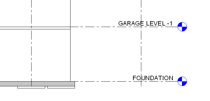
 - Click the foundation, and select the desired Foundation family type on the Family drop-down list. Note: Foundation slabs are added below the level in which they are drawn. Therefore, if you add a foundation slab in Level 1, it is added below Level 1 and will not be visible in the Level 1 plan view. To see the foundation slab in a plan view, create a new level below Level 1, for example, Foundation Level. When you create a new level below Level 1, you will also be able to see the foundation slab as an underlay (displayed in halftone) in Level 1.

Foundation slab below foundation level