In either a plan or 3D view, you can pick structural beams and walls to define the boundary of the structural beam system.
- Click Structure tab
 Structure panel
 Beam System.
 - Click Modify | Place Structural Beam System tab
 Beam System panel
 Sketch Beam System.
 - Click Draw panel
 Pick Supports. Tip: When picking supports, the first support you pick specifies the beam direction. The beams within the beam system will be parallel to this beam. You can modify this at any time. See Modifying a Beam System.
 - Pick the first support member.
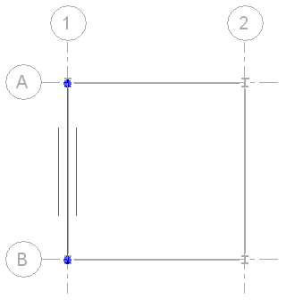
A sketch line with 2 drag handles displays over the picked support. Two shorter parallel lines display on each side of the line, indicating the beam system direction.

Beam system with first support member picked
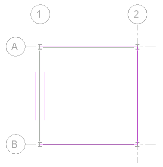
- Pick the remaining lines that define the beam system boundary. Note: The lines must result in a closed loop. Use the editing tools (Trim, Extend, and so on) on the Options Bar as necessary to create a closed loop of sketch lines. For more information, see Editing Elements.

Beam system with entire boundary selected
After specifying the beam system boundary, you can
- Modify the beam direction if necessary. For more information, see Specifying Beam Direction in a Beam System.
- Modify beam system properties if necessary. See Modifying Beam System Properties.
- Use either the Pick Support or Lines tool to sketch an opening in the beam system. For more information, see Cutting an Opening in a Beam System.
- Click Modify | Create Beam System Boundary tab
 Mode panel
 Finish Edit Mode.
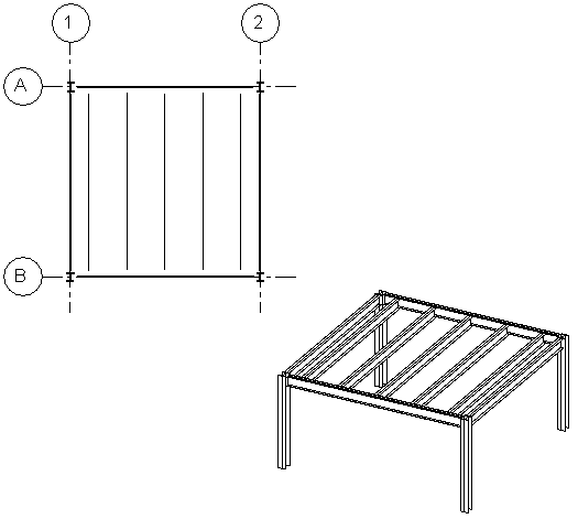
Floor plan and 3D view of completed structural beam system.