At launch, Robot presents a window of options to either open an existing structure or to enter one of the design modules.
There appears the dialog box, where:
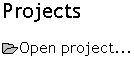
- The existing structure project can be selected (Projects option):
- one of recently edited projects can be indicated
- a project saved on disc can be selected (Open project option)
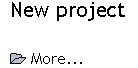
- Work on a new project can be commenced (New Project option)
- one of default structure types can be indicated (building, plate, shell or frame 3D) of recently edited projects can be indicated
- a new project type can be selected (More… option).
The Window presented below is opened after selecting the More... option.
When the cursor is positioned over a button, a tool tip prompt displays the name of the module.
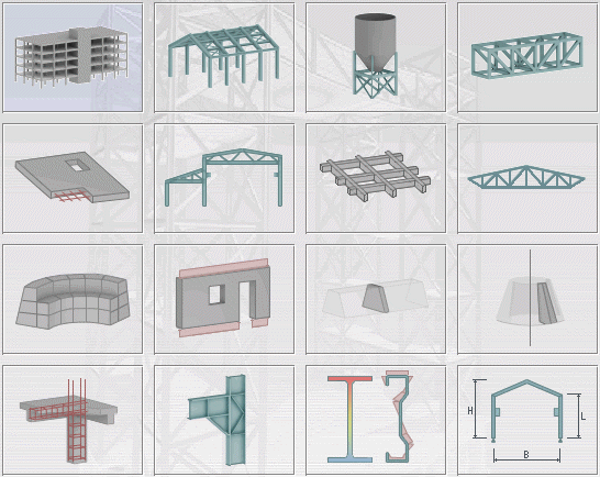
Structure Design
The top three rows of buttons (Frame 2D through Volumetric Structure) specify a style of structure design for you to build your module.
- a linear load is treated as a pressure of value 1 [N/mm / m] = 1000 [N/mm2]
- a concentrated load is treated as a linear load of value 1 [N/m] instead of [N/mm].
- A sum of reactions is interpreted analogously (always on the length of 1 m).
The axisymmetric structure type models a solid. It is generated due to rotation around the rotation axis, by means of a vertical 2D section through a solid.
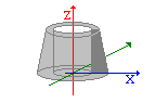
It is assumed that the global Z axis is a vertical axis of a solid; half of a section is defined on the positive side of the X axis. To mark the position of the vertical axis in an axisymmetric structure, auxiliary structural axes with X coordinates equaling 0 have been added.
Code Module Design
The next two buttons (RC Element Design and Connection Design) specify code modules for you to build your RC structure elements and steel connectors.
Section Design
The next button (Section Definition) allows you to specify bar section definitions (solid and/or thin-walled sections).
Parametric Structure
The final button allows you to create typical structures (simple frame 3D structures).
Once one of the code modules is selected from the start window, a module specific interface opens.
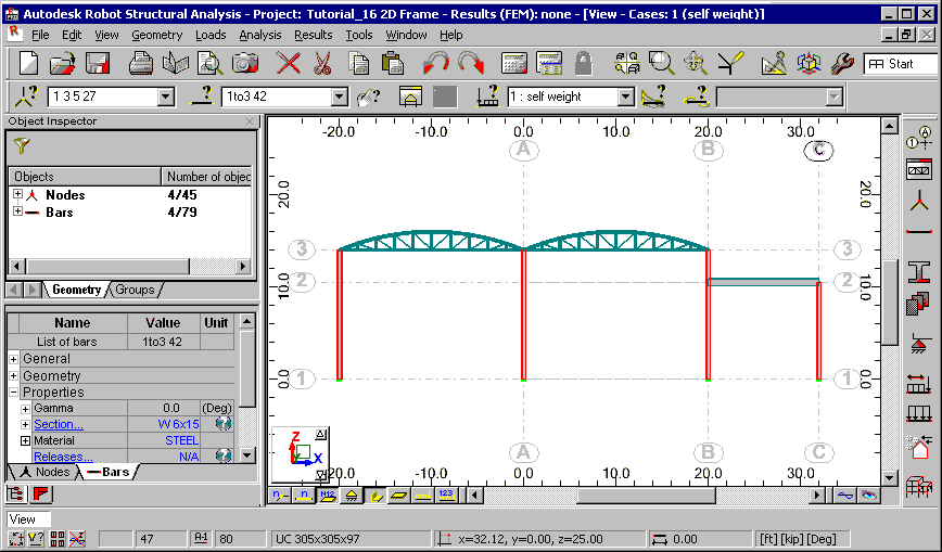
The interface is designed to simplify your workflow:
- The title bar displays general information pertaining to the project. This includes the project name and structure calculation data.
- The graphic editor is the display and editing area of the structure. Above the graphic editor is an array of menus, lists, and toolbars to facilitate design. The toolbar along the right side of the interface contains the most commonly used tools.
- Layout selection lists are located immediately above the graphic editor. These are user defined filters for selecting nodes, bars, load cases and eigenvibrations.
- The Object Inspector is located along the left-hand side of the interface. This contains a directory of the objects in a structure to select, view, and edit properties.
- Below the graphic editor is a set of buttons that control the views and display of a structure. The viewed elements include node/bar numbers, panel numbers, support symbols, section shapes, load symbols and values, as well as structure deformations for a given load case.
- The bottom of the interface presents information for quick reference, such as the names of active editing fields, cursor co-ordinates, and units. Several quick launch buttons are found here such as Display, Snap Settings, and the Graphical selection Filter.
Also see: