Use the Configuration dialog to define parameters applied during the verification of a steel member according to Eurocode 3 (EN 1993-1-1:2005). Access the dialog by clicking the Configuration button in the Calculations dialog. The following dialog displays:
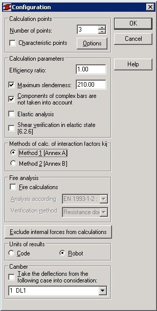
The following calculation parameters are defined.
- Calculation points; they are defined in two ways.
- By defining a number of points along the member length (the points are evenly distributed along the member length) - the Number of points option.
- By defining coordinates of characteristic points; select the Characteristic points option and click the Options button; the Calculations in characteristic points dialog opens.
- Efficiency ratio defines the coefficient by which the plasticity limit will be multiplied (increasing or decreasing the plasticity limit).
- Maximum slenderness; if the option is selected, the slenderness of a member is verified.
- Components of Complex Bars are not taken into account; if the option is selected, the components of complex bars are not considered during calculations of these bars.
- Elastic analysis; if the option is selected, the cross-section is classified as a class 3 cross-section. If the option is cleared, Robot checks each cross-section automatically and based on the cross-section class, calculates its strength in the plastic (class 1 and 2) or elastic (class 3 and 4) state. Note: The Elastic analysis option does not apply to sections classified as class 4. They are not reclassified to class 3 after selecting this option.
- Shear verification in the elastic state (6.2.6); if the option is selected, the shear stresses in the elastic state are checked according to point 6.2.6(d) of the code without considering the partial plastic redistribution of shear stresses.
- Methods of calculation of interaction factors kij; use this field to select a method of calculation of the interaction factors kij used in the formulas for verification of the global stability of a member under complex loading (compression and bending). These factors are included in the verification formulas (6.61 and 6.62) given in section 6.3.3.(4) of the EN 1993-1-3:2005 code. After selecting the method:
- Method 1 [Annex A], the kij factors will be calculated according to Annex A
- Method 2 [Annex B], the kij factors will be calculated according to Annex B.
- Fire calculations; selecting this option allows design and verification of steel members with user-defined sections according to the guidelines of the European code EC3 EN 1993-1-2:2005 or the official document 3 of the ECCS Technical Committee 'Model Code of Fire Engineering' - First Edition, May 2001. Parameters of the fire analysis are defined in the Member definition - fire resistance parameters dialog. It is possible to select a verification criterion used during the fire verification. There are three verification methods available.
- Resistance domain - verification according to section 4.2.3 of the EN 1993-1-2 code or sections III.5.1-7 of the document 3 of the ECCS Technical Committee
- Temperature/time domain - verification according to point 4.2.4 of the EN 1993-1-2 code or sections III.5.8 of the document 3 of the ECCS Technical Committee
- Time domain - verification according to point 4.2.4 of the EN 1993-1-2 code or sections III.5.8 of the document 3 of the ECCS Technical Committee.
Selecting the Fire calculations option excludes structure analysis in the serviceability limit state. Therefore, the Limit state - Serviceability option in the Calculations dialog will not be available.
- Exclude internal forces from calculations; click this button to open the Internal Forces Not Taken into Consideration dialog. This dialog includes options that define the limit values of internal forces (thus the force values that are 'negligible' for a specific section may be disregarded).
- Units of results; use these options to select the units for the presentation of results of the member design process. The results are presented in the units used in the indicated steel code, or in the units used in Robot
- Take the deflections from the following case into consideration; selecting this option activates a load case list. Use this list to select a load case (dead load), for which the calculated displacements will be treated as structure initial deflections.