To define a planar load:
- Case for which the load is defined
- Load distribution by defining the value of load intensity: px, py, or pz
- Plane to which the load is applied.
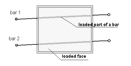
The plane is determined by the surface object (face) with the assigned type of cladding. The list of bars on which the forces from the loaded surface are generated is determined by the face definition itself. It is assumed that the load is generated on bars using calculation bar elements. Therefore, you can select a part of a bar within a contour. (See the following image.)

This information provides the basis for generating a trapezoidal load distributed over bars, which constitutes the system of forces statically equivalent to a load applied to the surface. The load, which is defined by using a plane, is automatically transformed into loads applied to individual bars.
A planar load applied to a plane is distributed onto bars using trapezoidal and triangular method - an engineering method, which assigns to beams, the trapezoidal loads applied to slabs.
A load from a surface can be applied to bars both as an isotropic load, that is, without specifying the distribution direction, or as an anisotropic load. The character of an anisotropic load assumes that there is a determined direction for transferring a planar load to bars. A corrugated plate is an example of an anisotropic surface. An anisotropy direction determines the direction of the fibers transferring load. The manner of distribution is determined by the cladding definition applied to a given surface. Loads acting on a face can be defined in the panel's (face) global or local system.