These guidelines in this topic apply to all three primary classifications of AEC models: mechanical, natural, and external ventilation. Flow boundary conditions, however, are specific to the application type, and are discussed in the respective application topics.
Overview
Apply thermal boundary conditions if an objective of the analysis is to understand the temperature distribution throughout the modeled space and/or on components or occupants. There are many potential heat-transfer-related objectives in AEC, and here are several typical examples:
- Heat generation and/or removal
- Thermal stratification
- Buoyancy-driven flows
- Air temperatures at inlets and other openings
- Temperature-dependent heat exchange (film coefficients, radiation)
- Specified heat exchange (solar loads, heating systems)
Basic Approach
The first step for using thermal boundary conditions is to understand and represent the known conditions within the model:
- Assign a known temperature to each inlet surface.
- Assign a heat generation boundary condition to each part that dissipates heat. Examples of such parts are heaters, electronic equipment, lighting, machinery, and humans.
- Assign boundary conditions such as film coefficients, radiation, and temperatures to the external surfaces of models that contain only an internal air volume. These conditions allow energy to enter and leave the space through exterior elements such as walls and windows.
See the Boundary Condition topic for more general information about these boundary conditions.
Surface-Based Thermal Boundary Conditions
For models that only include an internal (and omit external environmental conditions), assign boundary conditions such as film coefficients, radiation, and temperatures to external surfaces. These conditions allow energy to enter and leave the space through exterior elements such as walls and windows.
Commonly applied surface-based heat transfer conditions include temperature, film coefficient, radiation, and heat flux.
Apply surface boundary conditions only on exterior surfaces or to surfaces that are adjacent to suppressed parts (Such parts contact a meshed volume on one side and nothing on the other).
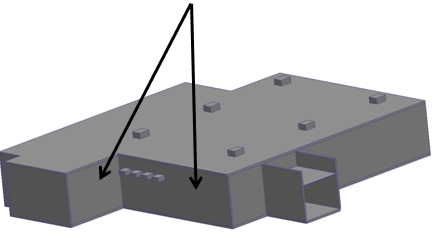
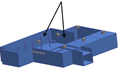
For example, if the walls, roof, and windows of a building are meshed, assign surface thermal boundaries around the exterior surfaces:

If, however, the walls, roof, and windows are suppressed (not meshed), assign surface thermal boundary conditions to the surfaces of the suppressed walls where they contact the internal air volume:

Volume-Based Thermal Boundary Conditions
Volume-based heat boundary conditions introduce heat into the model either on a per unit volume or total basis.
Use heat generation boundary conditions to model heat dissipated by components that produce heat. Examples include:
- People or gatherings
- A typical value is 100 W per person.
- Servers
- A typical range of values is 10-15 kW per 41U rack.
- Higher loads are anticipated in the future.
- Equipment, machinery, and lighting:
- Assign the power dissipated as heat, not the total power consumed.
- A 25% efficient LED light assembly, for example, dissipates 75% of the supplied power as heat.
- Cooking equipment
- Heaters
- Refrigeration equipment
- Use a negative heat generation value to remove heat from the model.
Be sure to set the selection mode to Volume (right click and select Volume as the Selection type).
For more about volume heat loads...
Frequently Used Surface-Based Boundary Conditions in AEC
Film coefficient
To simulate heat transfer to the surroundings, without actually modeling the surrounding environment, apply a film coefficient boundary condition to the external surfaces. The value depends on the air that surrounds the physical device:
- If the air is still, use a value of 5 W/m² K .
- If the air is moving, use a value of 20 W/m² K.
- Use a Reference Temperature = ambient temperature.
The amount of heat transferred depends on the magnitude of the film coefficient and the temperature difference between the specified reference temperature and the resultant temperature of the surface.
To account for both conduction through the volume as well as convection off the surface, assign a film coefficient boundary condition to the inside surfaces of suppressed walls, windows, or roofs. Assign a value that is the inverse of the R-value for walls or the U factor for windows:
- To simulate a wall with a total effective R value of R19, apply a film coefficient of 0.05 BTU/ft²/h/R.
- To simulate a window with a U factor of 0.30, apply a film coefficient of 0.30 BTU/ft²/h/R.
Remember that because film coefficients are based on difference in temperature difference, the absolute offset between Fahrenheit and Rankine drops out of the equation and the units BTU/ft²/h/R and BTU/ft²/h/F can be used interchangeably.
Temperature
Use temperatures to assign a known, uniform temperature to one or more surfaces. Typical applications include:
- Temperatures at openings
- Known (and fixed) exterior wall temperatures
- Suppressed parts that operate at a known temperature such as radiant panels, lights, piping, or machinery.
Radiation
Use a radiation boundary condition to model heat exchange with an arbitrary black body outside of the model. Radiation conditions act like film coefficients, and introduce or remove heat from the model based on the temperature difference. Note that the Radiation solver does not have to be invoked to use a radiation boundary condition.
A typical use of the radiation boundary condition for architectural applications is to simulate heat loss to the night sky. The temperature of a clear-night sky with no cloud cover can be as low as -40 °F with an associated emissivity of 0.3.
Heat flux
Use a heat flux boundary condition to model a heat addition or rejection through external faces.
A typical use of heat flux boundary conditions for architectural applications is to model solar loads (as an alternative to running the solar heating solver). To simulate the solar loading of direct overhead exposure (which is approximately 910 W/m²K), assign a heat flux value between 150-300 W/m² K. This range accounts for material finish, reflection, and atmospheric obstructions.