The Simulation CFD 2014 user interface contains numerous modifications that improve usability and consistency with other Autodesk products.
Autodesk Mouse Navigation
Upon installing Simulation CFD 2014, you will find that the default mouse navigation is now consistent with other Autodesk products:
-
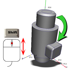
Rotate = Shift + middle mouse button:
-
Zoom = Roll the mouse scroll wheel:

Be default, zoom in to the model by rolling the scroll wheel toward you. To zoom in by rolling the wheel away from you, do the following:
- Click the Application Menu button (in the top left corner of the user interface).
- Click Options.
- On the User Interface Preferences dialog, click Navigation.
- From the Reverse zoom direction menu, select On
- Close Simulation CFD and restart it for the change to take effect.
-
Pan = Middle mouse button:

If you prefer the default mouse mode in Simulation CFD 2013, do the following:
- Click the Application Menu button (in the top left corner of the user interface).
- Click Options.
- On the User Interface Preferences dialog, click Navigation.
- From the Navigation mode menu, select CFdesign.
- Close Simulation CFD and restart it for the change to take effect.
To learn more about navigating with the mouse, click here.
Retire Classic User Interface
The Simulation CFD 2014 user interface is based exclusively on the Ribbon. By removing the toolbar-based Classic Interface, we are better able to focus on making your experience with Simulation CFD the best it can be.
New Ribbon Tabs
The Simulation CFD 2014 Ribbon has several new tabs. You can use these controls to help you learn the product, engage with the Simulation CFD user community, share results on Autodesk 360, and keep your simulations safe in Autodesk® Vault:
- Vault: Use the Vault tab to archive your Simulation CFD design studies (in ".cfz" form) in an Autodesk Vault. You can associate checked-in geometry files with your CFD design studies. You can also create or modify an existing design study with geometry stored in Vault.
- Autodesk 360: You can use these tools to share Simulation CFD design studies and results images. This is a powerful way to collaborate with others in your design supply chain.
- Start & Learn: These resources help you to learn Simulation CFD.
- Use the Start Here and Learning Map options to quickly learn the basics.
- Get hands-on practice with Tutorials.
- View demonstrations of important techniques in Videos.
- Click Help to access Simulation CFD Help.
- Community: Engage with other Simulation CFD users. Post your questions, exchange ideas, and explore the Autodesk Labs site. Enroll in the Customer Involvement Program to help us improve the product based on how you use it.
- The IdeaStation is an online system for sharing your insights and enhancement requests about all Autodesk products. You can provide your feedback on product functionality, quality, and whatever else you feel needs improvement. To learn more about IdeaStation, click here.
- Add-Ins: These are small applications that introduce new functionality into Simulation CFD. Some are developed by the Autodesk team, but you can also develop add-ins to customize the product to meet your specific needs.
To learn more about the Simulation CFD ribbon, click here.
Autodesk Navigation Tools
These tools provide a wide range of options for interacting with your models in Simulation CFD. They are part of a standard set of tools found across Autodesk Simulation products.
Navigation Bar
By default, the Navigation bar appears on the right side of the model window. It contains tools for controlling the model position, zoom, orientation, and appearance.
The Navigation bar contains the following controls:
- SteeringWheel: Collection of wheels for rapid switching between specialized navigation tools.
- Pan: Moves the view parallel to the screen.
- Zoom tools: Set of navigation tools for increasing or decreasing the magnification of the current view.
- Orbit tools: Set of navigation tools for rotating the current view.
- Look at: Reorients the model so that the selected face is parallel to the viewing plane.
- Center: Set the center of rotation (pivot point).
Because the Navigation bar brings these tools directly to the model, you can easily interact with your simulation without changing the active tab or disrupting your current workflow.
To learn more about the Navigation bar, click here.
Steering Wheels
The Steering Wheels, also known as wheels, combine many of the common navigation tools into a single interface. They contain the Pan, Zoom, Orbit, and Rewind tools in a convenient interface that follows your cursor. Wheels provide highly interactive model navigation without having to move your mouse away from the model or enter a navigation mode. You can access wheels from the Navigation bar and from the View tab.
To learn more about Steering Wheels, click here.
ViewCube
The Autodesk® ViewCube® navigation tool is a convenient, highly functional way to navigate your model and to adjust the viewpoint. You can use the ViewCube to quickly orient in any of 26 pre-set orientations, rotate the model about the Cartesian axes, and reset the model to its default orientation.
To learn more about the ViewCube, click here.
New Navigation Controls on the View tab
The View (tab) > Navigation (panel) has several new tools. This makes the tab more consistent with other Autodesk Simulation tools:
- SteeringWheel: Collection of wheels for rapid switching between specialized navigation tools.
- Pan: Moves the view parallel to the screen.
- Zoom tools: Set of navigation tools for increasing or decreasing the magnification of the current view.
- Orbit tools: Set of navigation tools for rotating the current view.
- Look At: Reorients the model so that the selected face is parallel to the viewing plane.
To learn more about the View tab, click here.
Trigger Scripts
The API has been expanded to include the ability to automatically launch a script when a specific event occurs. To access the Triggers dialog, click Setup (tab) > Design Study Tools (panel drop down menu) > Script Editor. On the Script Editor, click Tools > Triggers...
Examples of using trigger events:
- Use a trigger to detect when the simulation finishes so that a script can automatically extract results or save a specific data item. This automates data extraction, and eliminates manual intervention.
- Use a trigger to detect when the geometry model is loaded to execute a script that automates the setup and execution of the simulation. This is useful if you are automatically varying geometric parameters from a CAD tool.
To learn more about Trigger Scripts, click here.