The User Interface Preferences dialog contains many ways to customize the user interface to suit your work habits and working environment.
Display
Perspective view
Choose to enable or disable perspective view by default.
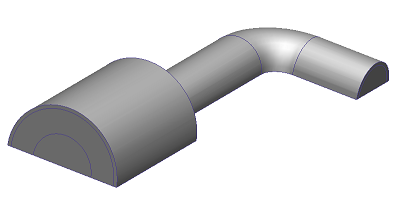
Perspective provides "depth" to the model by reducing the size of objects that are further away from the viewer. It provides a more physically realistic view. When perspective is disabled, the model is displayed orthographically. This means the model entities are displayed as their actual sizes. This is useful for making selections when the model is aligned to a Cartesian axis.
Orthographic:

Perspective:

Preserve blanking when changing selection mode
Select Yes to cause blanking to persist when the selection mode is changed.
Blank edges when blanking volumes
Select Yes to cause edges to blank when the volume that owns them is blanked. This improves visibility of internal features when adjacent parts are hidden.
Show coordinate axes
Select Yes to display the coordinate axes by default.
Number of legend levels
Use this to set the default number of legend levels when visualizing results. The default is 24 for new models.
Background color
Select CAD Dependent to use the background color from the launching CAD system.
When an existing design study is opened, the background color persists from the previous session. The background color for a new design study (not launched from one of these CAD tools) is the default color specified in the Background Color dialog.
Select User Defined to use the background color specified in the Background Color dialog
Show Initial conditions task icon
The default value of No hides the Initial Condition control from the Setup tab.
To show the Initial Conditions control by default:
- Change the value to Yes.
- Click OK.
- Exit and restart Autodesk Simulation CFD.
Show Motion task icon
The default value of No hides the Motion control from the Setup tab.
To show the Motion control by default:
- Change the value to Yes.
- Click OK.
- Exit and restart Autodesk Simulation CFD.
Show Geometry tool if applicable
The default value of Yes automatically displays the Geometry dialog if a potential geometry issue is found. This only occurs when the model is first launched into the software.
Units
Startup length units
Select the default length units. The choices are: meter, cm, mm, foot, inch-BTU/s, and inch-Watt.
Results Units
Use the Results Units dialog to specify the default units of result scalars. Because many companies have guidelines for how results are communicated internally, it is convenient to set the default on this dialog so a manual change is not necessary with every analysis.
The Default choice is the first item for every quantity, and is shown if no unit system is selected. Quantities with the Default selection are displayed using the default units of the current units system.
Units selected for a quantity are applied to all related quantities as well. For example, if mm/h is selected as the default for velocity, then all velocity components as well as absolute velocity will be displayed in mm/h. Related quantities are shown in the table:
| Velocity | Velocity Magnitude |
| U-Velocity | |
| V-Velocity | |
| W-Velocity | |
| Absolute Velocity Magnitude | |
| Absolute Velocity in X-dir | |
| Absolute Velocity in Y-dir | |
| Absolute Velocity in Z-dir | |
| Pressure | Static Pressure |
| Total Pressure | |
| Absolute Static Pressure | |
| Viscosity | Viscosity |
| Effective Viscosity | |
| Conductivity | Conductivity |
| Effective Conductivity | |
| Temperature | Temperature |
| Total Temperature | |
| Shear Stress | Shear Stress |
| Wall Shear Stress |
Navigation
Navigate as wireframe
The default setting of Off preserves the current model appearance during model navigation.
Select On to automatically display the model as outline during navigation.
Navigation mode
This sets the default mouse mode when is started. Select a CAD system to use the mouse navigation mode from a specific CAD system.
In addition to the default mode (Autodesk Simulation CFD), several modes that mimic supported CAD systems are available.
Reverse zoom direction
By default, rolling the scroll wheel away from you causes the model to zoom out (get smaller on the screen). Some CAD systems, however, use the opposite convention, and zoom in when you roll the scroll wheel away from you. To enable this behavior, select On from the Reverse zoom direction menu.