Use Simulation CFD Results for Stress Simulations
Excessive temperature gradients in solid objects cause stresses which can lead to material failure. To simulate the effect of thermal stresses, you can now use results from your Simulation CFD heat transfer simulations as Autodesk® Sim 360™ thermal loads.
After the CFD simulation finishes, you first need to export your results:
- Click the Application Menu button in the top left corner of the user interface.
- In the Application menu, click Export. Click CFD Data Package.
Simulation CFD saves your results as a data package file. You can then import the data package into your structural simulation model in Simulus.
For more about Stress Simulations, click here.
You can also use temperature results from your Simulation CFD analysis as the basis for a thermal stress analysis in Autodesk® Simulation Mechanical. After completing your heat transfer analysis in Simulation CFD, launch the CAD model in Simulation Mechanical, assign the settings to define the thermal stress analysis, and select the Simulation CFD design study file as the temperature source. For additional information about Simulation Mechanical interoperability, click here.
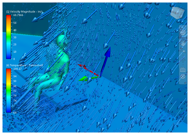
Model Walk-Through Capability
A striking way to visualize the flow inside a device, enclosure, or structure is with the walk-through capability. With this method, you view the results as if you physically inside the model.
To "enter" the model:
- Ensure Perspective view is active.
- To invoke Perspective, click the menu arrow on the lower, right corner of the ViewCube, and check Perspective.
- Zoom into the model past the outer surfaces. You can use the mouse scroll wheel, the View tab Zoom command, the Navigation bar Zoom command, or the Zoom command on a SteeringWheel. Note that you may have to zoom in several steps before "entering" the model.
You can move around to view the internal features of the model with the pan, zoom, and orbit commands. You can also use the "Look" and "Walk" commands on the SteeringWheels.
To learn more about SteeringWheels, click here.
Display Wall Heat Flux as a Vector
To visualize both the direction and magnitude of heat flux, display the Wall Heat Flux vector quantity. This is available on the Vector Results menus for Global, Planes, and Iso Surfaces.
Wall Results Accuracy Improvements
Simulation CFD 2014 contains improvements to the force and heat flux computations on wall surfaces:
- Heat flux and force results computed while the simulation is running are more consistent with results reported after the simulation is complete.
- The weighting functions are improved to account for forces and fluxes near surface boundaries and to improve accuracy.
- Wall force runtime results account for shear forces.
To learn more about the Wall Calculator, click here.