Previous: Exercise 3 | Next: Exercise 4
Prior to running an Autodesk Simulation CFD analysis, the geometry is broken up into small pieces called elements. The corner of each element is a node. The calculation is performed at the nodes. These elements and nodes make up the mesh.
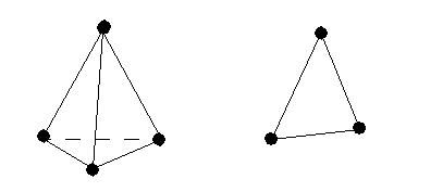
In three dimensional models, most elements are tetrahedrals: a four sided, triangular-faced element. In two dimensional models, most elements are triangles:
Advantages of Automatic Mesh Sizing
Autodesk Simulation CFD performs a comprehensive topological interrogation of the analysis geometry and determines the mesh size and distribution on every edge, surface, and volume in the model. Geometric curvature, gradients, and proximity to neighboring geometry are all considered when assigning element sizes and mesh distributions.
- Greatly simplified set-up of analysis models resulting in less time spent assigning mesh sizes.
- More efficient mesh distributions--the mesh is fine where required, and coarse where it can be.
- Improved solution accuracy due to better mesh quality and mesh transitions.
- Improved solution robustness--good mesh transitions lead to a well-posed mathematical model.
It does not matter which selection mode (volume, surface, or edge) is active when this button is clicked.
This process is fast, but can take a few minutes for models that contain more than 3000 edges.
The Mesh Workflow
Automatic Sizing
There are several ways to apply Automatic Sizing:
- In the context panel, verify that the Type is set to Automatic. Click Autosize.
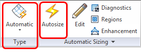
- Left click on or near the model, and click the Automatic icon on the context toolbar:

- Right click in the Graphics window or on the Mesh Size branch of the Design Study bar, and click Edit.... Click Automatic size on the Mesh Sizes quick edit dialog.
Mesh Tools
Use the Mesh Tools to customize the mesh distribution. All tools are accessible from the Mesh Sizes quick edit dialog. To simplify the workflow, many are also available on the context tool bar and on the context panel.
Context tool bar
Left click on or near the model:

- Open the Mesh Sizes quick edit dialog.
- Invoke automatic mesh sizing.
- Create mesh refinement regions. (To focus the mesh in critical locations.)
- Check the model with Diagnostics. (To remove potentially problematic features.)
- Suppress a selected part. (To remove less important parts, and decrease the analysis time.)
- Resume a selected part.
Context panel in the Ribbon
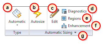
- Toggle between Automatic mesh sizing and Manual mesh sizing.
- Invoke automatic mesh sizing.
- Open the Mesh Sizes quick edit dialog.
- Check the model with Diagnostics. (To remove potentially problematic features.)
- Create mesh refinement regions. (To focus the mesh in critical locations.)
- Modify or disable Mesh Enhancement .
- (In the expansion panel of the context panel.) Customize the mesh distribution by modifying Advanced meshing controls.
On-model mesh modification
In some cases, the mesh distribution needs to be modified:
- Select the part.
- Open the Mesh Sizes quick edit dialog.
- Make the appropriate refinements or invoke Automatic Refinement.

Mesh History
When you define a mesh with Automatic Mesh Sizing, you define a process that the Mesher uses to generate the mesh. Unlike materials and boundary conditions, a mesh definition is a set of commands issued in a specific order. When you change the order of these commands, you often change the resultant mesh.
The Mesh Size branch of the Design Study bar lists every step in the mesh definition history. This includes when Automatic Sizing is invoked, size adjustments, and when Spread Changes is applied. Each step is listed as a separate branch, and can be modified, disabled, or deleted from the mesh definition.
All steps in the history constitute the mesh definition. Certain mesh definition commands prompt question dialogs regarding the re-institution of existing adjustment settings or the removal of existing mesh sizes. The responses to these questions affect the current mesh definition, but they do not remove earlier steps in the history. New steps are added to the definition may change the distribution and may even "undo" the effects of earlier steps.
These are the primary benefits of the Mesh History:
- You have full visibility to every step that defines the mesh. This makes it easy to recreate the same mesh on a different model or at a later time.
- You can "roll back" a mesh definition by disabling or eliminating one or more steps. This makes it easy to see the effect of a change or to fix errors.
To change an existing setting in the mesh distribution:
Most mesh distributions on complex models are defined through a series of commands and refinements. Because every setting is accessible in the History, it is easy to modify a specific setting in the mesh definition.
- Right click on the setting, and select Edit.
- Modify the value in the dialog.
To rebuild the mesh distribution:
When a setting is modified or deleted, a "warning" icon is displayed over the Mesh Size branch:

This means that the mesh distribution is out of date and needs to be rebuilt.
- Right click on either the Mesh Size branch or in the model window.
- Click Rebuild mesh definition.
To disable a setting:
Sometimes it is useful to temporarily remove a setting without deleting it. This can be help determine the effect a setting has on the mesh distribution.
- Uncheck the box adjacent to the setting.
- Rebuild the mesh distribution.
To modify an existing mesh refinement region:
- Right click on the region branch in the Design Study bar, and select Edit.
- Modify the region settings in the dialog, and rebuild the mesh definition.
Tools for Improving the Mesh
It is important to have enough mesh to capture flow and heat transfer gradients. It is also important to conserve computer resources so that analyses run quickly. Autodesk Simulation CFD provides tools to help you modify the default mesh to match your design and optimize performance and reliability.
- Locally adjust mesh sizes to accommodate flow details that need additional mesh density
- Extrude linear parts that have uniform cross sections
- Create refinement regions for concentrating the mesh locally
- Modify the Minimum Refinement Length to adjust the threshold edge size that will be allowed to influence the mesh in neighboring features. This is one of the most powerful tools for improving the mesh.
To locate problem areas in CAD geometry, click the Diagnostics button. This set of tools interrogates the geometry to determine the location of potential problem areas. These areas may cause difficulty in the determination of mesh sizes, the mesh generation, and in the solution stability of the analysis.
Use the Suppress tool to prevent one or more parts from being meshed. Part Suppression eliminates parts from the analysis, but they will appear (unmeshed) in the results.
Visualizing the Mesh
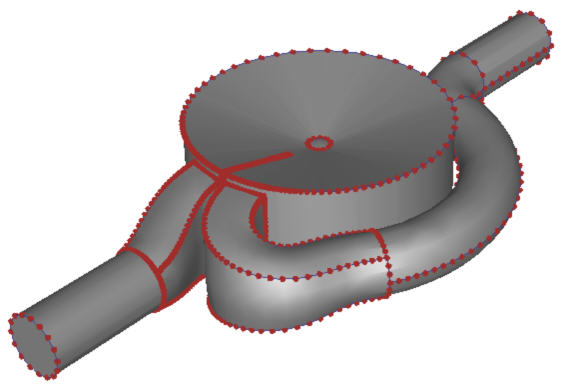
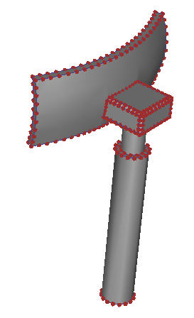
During the Mesh task, preview dots appear on the edges of all volumes to be meshed. These dots indicate the location of nodes on edges once the mesh is generated.
|

|
|
|

|
|
To view the mesh prior to generating the entire three-dimensional mesh:
- Select surfaces or volumes.
- Right click, and select Preview.
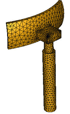
The mesh faces are displayed on the selected surfaces. Note that if volumes are selected, the element faces are drawn only on the surfaces of the selected volumes.
To remove the previewed element faces:
- Select the surfaces or volumes that are displayed with a previewed mesh.
- Right click, and select Clear.
Generating the Mesh
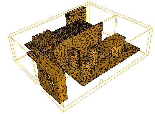
To generate the mesh, click Solve on the Solve dialog. The mesh is constructed according to the prescribed element distribution. If a mesh already exists (and you are simply continuing the analysis), then a new mesh is not created.
To view the mesh prior to running the analysis:
- Right click on the Scenario branch or the Mesh Size branch in the Design Study bar.
- Click Generate mesh.
This is a good opportunity to check the mesh to ensure that it resolves the geometry adequately.
Related Topics