A series of linearly varying beam cross-sections can be created using the Variable Cross-Section Wizard. Each beam element has a different cross-section dimension based on interpolating the two user-specified end dimensions. The wizard creates a stepped beam that approximates a tapered beam. Any user-defined shape (rectangle, wide-flange beam, channel, pipe, and so on) whose dimensions can be entered in the normal cross-section library dialog box can be used for the variable cross-section.
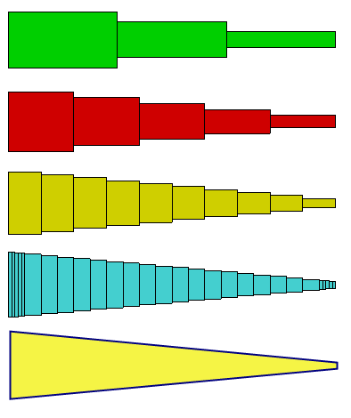
Figure 1: Variable Cross-Section Beam - four different mesh densities are shown to simulate a tapered beam with a variable height (bottom figure).
To generate the variable cross-sections
- Draw the tapered beam member on a unique part number. Use the surface number necessary for the proper orientation (see Beam Element Orientation on the page Beam Elements), but any layer number can be used. (The layer number is by the wizard.) all the lines in the part must connect together so that there are just two endpoints. The lines must be continuous and not branch or create a loop. They are not required to be in a straight line.
- Divide the member into the number of elements needed. Since the taper is approximated, the results are more accurate if more elements are used.
- Set the Element Type to Beam.
- Select the part (Selection
 Select Parts), right-click, and choose Variable Cross-Section Wizard.
 - Select the type of cross-section to use from the drop-down.
- Enter the dimensions of the cross-section for Vertex A and Vertex B. Note the symbols A and B added to each end of the part in the display area. A dimension of 0 cannot be used for some sections; enter a small value instead.
- Click OK.
The wizard changes the model.
- Each line segment of the part is changed to a unique layer number, starting with layer 1, and ending with layer n.
- The cross-sectional dimensions for the n layers are interpolated at the midpoint of each segment using the cumulative length from point A to the midpoint.
- The cross-sectional properties for the interpolated dimensions are calculated and entered into the Sectional Properties spreadsheet of the Element Definition. Additional input may be required in the Element Definition to complete the definition of the beam.
Note:
- Once the wizard completes, the part is identical to what is created by hand if you chose to enter the input for each element. I any manual changes are made to the part , such as making the member longer or shorter, rerun the wizard to compute the new values.
- Since the cross-section is calculated at the midpoint of each element, the stress at each end of the element is either an overestimate or underestimate of the theoretical result. Use more elements in the part to minimize the approximation.