In Step 2 of Fatigue Wizard, enter the material properties to use in the fatigue analysis. The form presented depends on the type of fatigue analysis you chose in Step 1.
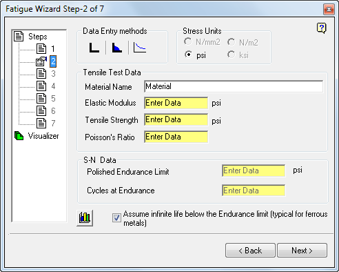
For example, different material data is required for the definition of a strain-based analysis than a stress-based analysis. The Fatigue Wizard tailors the form presented at Step 2 to highlight only the data that is required for the chosen analysis type.
However, some inputs to this step are common to all analysis types.
Stress Units
The units system is picked up automatically from the Simulation Mechanical stress files. Therefore, the appropriate stress units are preselected, and all other units are unavailable for selection (grayed out). The Model Units in your Simulation Mechanical analysis must be consistent with those available within Fatigue Wizard in order to perform a valid fatigue analysis. For example, you must avoid using dynes and microns (µ).
The following units are supported by both Simulation Mechanical and Fatigue Wizard:
| Force Units | Length Units | Stress Units (derived from force and length unit specifications in Simulation Mechanical) |
|---|---|---|
|
|
|
Material Graph
As a visual check of the material data being entered into the Fatigue Wizard, show the data graphically by clicking on the chart button  .
.
Material Databases
You can enter the required data directly into the relevant boxes on the form. Or, if available, select a predefined material from the editable material database. Use the buttons in Data Entry methods to select the material databases:
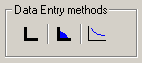
Select from Load parent material data from the database, Weld material data, or User-Defined S-N data, respectively.
To import data, select the appropriate icon. In the dialogbox, select a material from the list of available options.
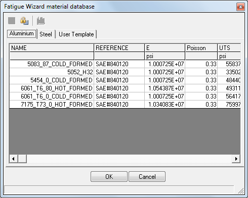
The following is a typical view of the parent material database:
To edit or create a material database
- Click the Lock icon.
- Make the appropriate changes to the table.
- Click the Save icon.
- Enter a new file name to create a database, or accept the existing file name. Note: Save all material database files to the [install folder\Addins\Fatigue Wizard] folder. If you save material database files to other locations, they are not read into the Fatigue Wizard.
- Click Save.
You can also select Weld material data (Stress based method only).
The weld material database is shown in the following image:
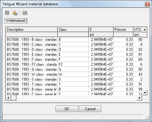
The weld SN curves are mainly taken from BS 7608 : 1993 Code of Practice for Fatigue design and assessment of steel structures.
If unit information can be derived from your FE model, then Fatigue Wizard automatically selects them. Alternatively, material data values can be automatically converted to four common unit systems by selecting the appropriate option.
The material data selected is then placed automatically into the relevant input boxes. You can still enter your own data values.
The material data entered varies, depending upon your choice of analysis method in Step 1.
User-Defined S-N data input (Stress based method only):
Before selecting this third input option, you must first specify a nonzero Tensile Strength for the material. Then, click the User-Defined S-N data icon. The following dialog box appears:
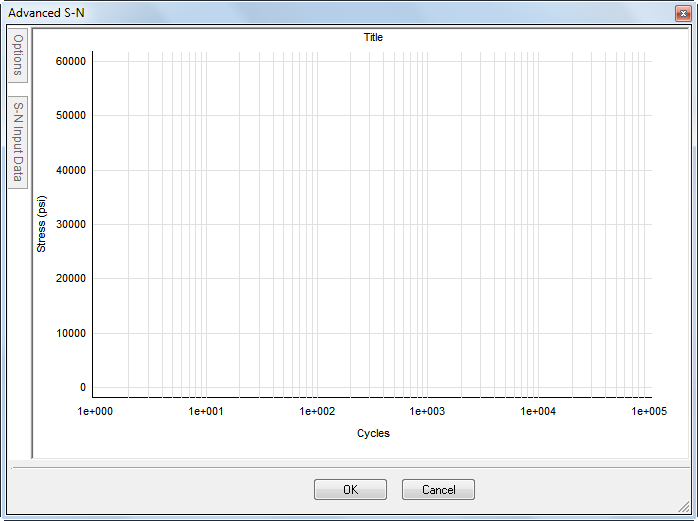
The two tabs along the upper-left edge are used to access pull-out dialog extensions.
Use the Options tab to set whether the X and Y scales are linear or logarithmic.
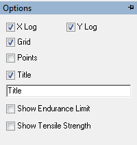
In addition, you can choose to include a grid, mark all data points, or mark the tensile strength or endurance limit data points. Finally, you can specify a title for the SN curve within this tab.
Use the S-N Input Data tab to enter the Cycles versus Stress data points into a table.
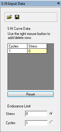
Right-click in the table to insert a row, delete a row, or reset (clear) the table. You can also import the table from a *.CSV file (comma-separated values), or export the table to a *.CSV file. There are two fields below the table that you use to define the endurance limit—Stress and Cycles. Input one value, and the other is calculated by the program. The radio button to the right of each field specifies which quantity is to be calculated. If you specify a number of cycles or a stress value that lies between two rows of the table, the program will interpolate between the data points. The program will not extrapolate for values outside of the range of cycles and stresses entered into the table.
Additional SN (Stress Based Life) Data Entry
If you elect to perform a stress-based life calculation in Step 1, you are required to enter two further inputs for the SN material data in addition to the Elastic Modulus, Tensile Strength, and Poisson's Ratio:
- Polished Endurance Limit
- Cycles at Endurance
For more information on these material properties, see "Theoretical Overview: Stress Based Fatigue Analysis".
Select the "My material is a Steel" check box to alter the way in which the SN curve for the material is defined beyond the endurance limit. When selected, the SN curve follows a horizontal line beyond the defined endurance limit. That is, below the endurance limit of the material, there is no damage. Therefore, the material exhibits infinite life.
Assume infinite life below the Endurance limit (typical for ferrous metals): Check this box if your material is a steel or similar ferrous metal. For such metals, the fatigue life is typically assumed to be infinite at stresses below the endurance limit (no damage). If you do not activate this checkbox, the SN curve is modified at stresses below the endurance limit to give a different slope. The slope used, below the endurance limit, is proportional to (2k-1) where k is the slope of the main SN curve. Therefore, fatigue damage can still occur beyond the endurance limit, but to a lesser degree.
EN (Strain Based Life) Data Entry:
If you elected to perform a strain-based life calculation in Step 1, you are required to enter two further EN material properties in addition to the Elastic modulus and the Ultimate tensile strength.
To input the required data to describe the strain-life curve, you have two options: the Approximate method and the Advanced method.
Approximate Method:
Because the methods used to determine strain-life data are expensive, and the time that this method has been widely used is relatively short, this material data is often difficult to find for non-standard materials. To overcome this problem, several methods have been adopted which approximate the strain-life data from the readily available monotonic data (modulus and tensile strength).
The Fatigue Wizard uses one of these empirical methods. If the material that you are using is not included in the materials database, select the 'Approximate' button on the form. This forces Fatigue Wizard to calculate approximate data for the strain-life curve. With this empirical method, in some cases, inaccuracies occur in the final fatigue results. As with all fatigue analysis, accurate material data is crucial.
TheAssume infinite life below the Endurance limit (typical for ferrous metals): option is important if you use the Approximate method. The empirical method uses different data for steels and non-ferrous materials. In a similar way to the SN curve exhibiting different behavior at high cycles, the EN curve shows different trends for ferrous and non-ferrous materials. Therefore, activate or deactivate this check box appropriately.
Continue to the Advanced and Approximate Strain-Life Data page for more information.
Advanced Method:
If you have access to advanced strain-life data for a material that is not included in the database, then you can enter the data directly in Step 2 of Fatigue Wizard. In this case, select the Advanced radio button. A separate form opens for entry of the six parameters required to describe the cyclic stress/strain and strain-life curves.
Continue to the Advanced and Approximate Strain-Life Data page for more information.
See a more complete description of the advanced parameters (such as Cyclic Hardening and Fatigue Ductility coefficients) in the Theoretical Overview: Strain Based Fatigue Analysis page.
Fatigue Safety Factor Data Entry
If you elected to perform a fatigue safety factor calculation in Step 1, the material data input for the fatigue safety factor calculation requires the same data as the SN life calculation method (elastic modulus, tensile strength, Poisson's ratio, endurance limit, and number of cycles to failure), with the added requirements necessary to describe the infinite life curve.
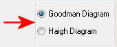
There are two methods to calculate a fatigue safety factor. You can select a basic Goodman diagram, or a more advanced method in which you define a Haigh diagram (with greater flexibility).
Goodman Diagram option
If you select the Goodman Diagram option, Fatigue Wizard sets up with a traditional Goodman diagram for its calculation of fatigue safety factor (FSF). The following is an example of a Goodman diagram.
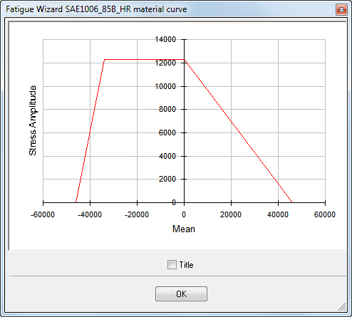
The Goodman diagram uses the same value for strength in both tension and compression. This factor is a severe limitation for materials such as cast iron, which is much stronger in compression than in tension.
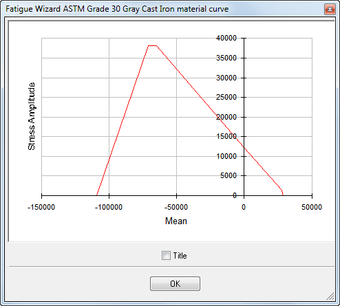
Haigh Diagram option
If you require more control over the shape of the infinite life curve, select the Haigh Diagram option. Although this method does not provide complete control over the definition of the shape of the curve, it is more versatile than the Goodman approach. This versatility is important for materials such as cast irons, which show different monotonic properties in tension and compression. Using the Haigh Diagram method, it is possible to define separate values for ultimate strength and yield strength in both tension and compression.
When you select the Haigh Diagram radio button, a separate form opens, where you can input the additional data. On this additional form, the boxes for Tensile Strength (UTS) and Fatigue Endurance Limit are automatically filled with the data from the main form of Step 2. Therefore, we recommend that you complete all data required on the main Step 2 dialog box before you access the Haigh Diagram Data entry form.
The compressive data, both Ultimate Compressive Strength and Compressive Yield Strength, are entered as magnitudes with no account of sign. Fatigue Wizard automatically assigns a negative sign to the compressive values.
If you select the Haigh Diagram option on the main form, you must enter the additional properties before you proceed to the next steps of the fatigue analysis.
The following is an example of a Haigh Diagram.
For more details about creating Haigh diagrams and the theory of the fatigue safety factor calculation, see "Theoretical Overview: Fatigue Safety Factor".