In step 3, if you perform fatigue analysis on stress results from a finite element program, consider any geometric effects that are ignored in the stress results.
For example, it is possible that the finite element model does not perfectly represent the geometry of the part being analyzed. It can miss geometric features that lead to stress concentrations. Examples are features such as:
- Fillets
- Holes
- Notches
- Threads, and so on
If these features are not present in the finite element model, modify the stress results to take the effects of these features into account.
You can use accepted values of stress concentration associated with the features type and dimensions. These values are readily available for many different geometric features in texts such as Roark or Peterson.
A value of Kt is used to convert the nominal stresses.
You can use the same approach in the fatigue analysis. However, some materials exhibit different sensitivity to stress concentration with respect to fatigue life. That is, the same geometric stress concentration changes the fatigue life differently, according to the material type. This effect is known as a notch sensitivity.
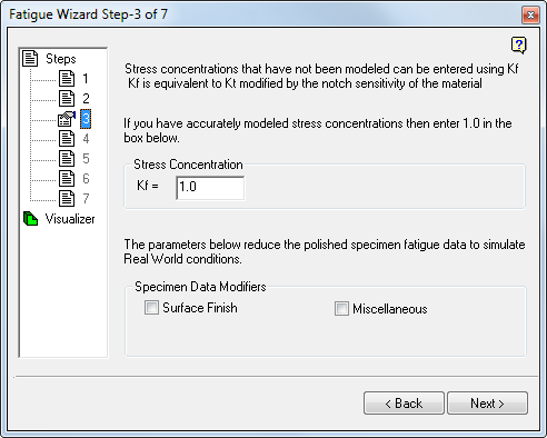
To take account of the notch sensitivity, it is common to apply a factor Kf to the finite element results: Kf being equivalent to Kt, but factored to take account of the notch sensitivity of the material. If a value of Kf is not known, you can be conservative and apply the Kt value.
The Kf value is entered into Fatigue Wizard in Step 3 using the box shown:
Kf>=1.0
If you are certain that the finite element model is accurately predicted stresses, then use a value of 1.0 (default) for Kf.
In addition to the stress concentrations normally associated with small geometric features, there are a number of additional factors to account for in a fatigue analysis. All of these additional factors have a potential to modify the nominal material properties obtained from specimen testing.
Normally, SN and EN material data are previously measured using specimens of a standard size, standard temperature, and standard polished surface finish. In a ‘real’ engineering component, if the conditions are not the same as these ‘ideals,’ use some means of factoring the materials properties (from test).
These factors are sometimes referred to as the endurance limit modifiers. You can add an endurance limit modifier for surface finish. Use the drop-down menu, or apply any other modifier using the ‘miscellaneous’ option.
Surface Finish
Fatigue Wizard is coded with a variety of surface finish modifiers, which you can quickly choose. Use the drop-down menu, and choose the appropriate finish for the component (or surface) you are analyzing.
Miscellaneous
To take account of any further endurance limit modifiers, input a further single value under the ‘miscellaneous’ input. Enter a single value between the range 0 and 1.0.
- Size effects
- Temperature effects
- Loading effects
- Reliability of data
A more complete description of these effects, and the values associated with each, is available in most engineering texts on fatigue analysis.
Combination of modifiers in Fatigue Wizard
When you apply modifiers within Fatigue Wizard, understand how they affect the analysis, especially if you apply them in combination.
For more information on endurance limit modifiers, see "Theoretical Overview".