Given: A water-cooled, refractory wall in a furnace is subjected to the conditions shown in the following figure. Assume that the cold face remains at 125°F.
Find: The heat gained by the water per foot of pipe.
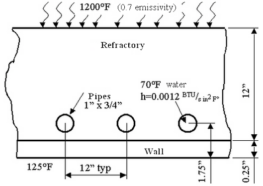
| Material | Wall (Part1) | Refractory (Part 2) | Pipe (Part 3) |
|---|---|---|---|
|
Conductivity (BTU/s in °F) |
6.254E-4 |
1.1E-5 |
6.254E-4 |
| Table 1: Material Properties | |||
Solution Procedure
This example only covers creating the model. For instructions on setting up and performing the analysis, see Water-Cooled Wall with Radiation, Convection and Temperature.
Each cross section is identical. A 2D planar analysis can be performed. Due to symmetry, only the cross-section around a single pipe is modeled, as shown in the following. The outline of each material is drawn, and the model is meshed with the 2D mesh generator.
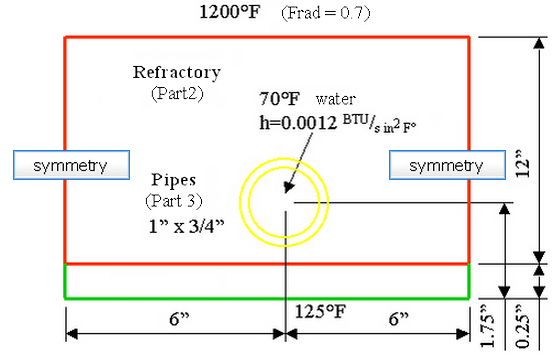
Wireframe of Model (Not to Scale)
- Start a new FEA model.
- Set the analysis type to Thermal: Steady-State Heat Transfer.
- Set the unit system to be consistent with the problem statement. Click Override Default Units and select English (in BTU) from the Unit System drop-down menu. Click OK to set the units.
- Click New and enter a model name.
- Start a new sketch. Right-click Plane 2 <YZ(+X)> in the Planes branch in the tree view and select Sketch. The sketch plane is shown with the grid. Choose YZ<+X> for 2D elements.
- Add a rectangle for the wall using the Draw
 Draw Rectangle command. Ensure that the Part number is set to 1 and the Use as Construction check box is selected. Enter the first corner at (0,0,0) and the second corner at (0,12,0.25). Click Apply to finish the rectangle.
 - Add a rectangle for the refractory. Set the Part number to 2. Enter the first corner at (0,0,0.25) (or snap to the existing corner of the wall) and the second corner at (0,12,12.25). Click Apply to finish the rectangle.
- Click the X button to close the Add Rectangle dialog box.
- To see the entire model, use View Navigate Enclose.
- Add the hole in the refractory with the Draw Draw Circle Center and Radius command. Make sure that the Part is set to 2 and Use as Construction is checked. Enter the two points at (0,6,1.75) (the center) and (0,6,1.25) (a convenient point on the perimeter of the hole). Click Apply to finish the circle.
- The outside of the pipe is in contact with the inside of the hole, so the same size circle must be drawn on part 3. Set the Part number to 3. Click the two construction vertices created with the previous circle to add the new circle on top. Click Apply to finish the circle.
- Add another circle for the inside of the pipe. Use the center of the existing circle and the point (0, 6, 1.375). Click Apply to finish the circle.
- Click the X button to close the Define a Circle dialog box.
- Finish the sketch by right-clicking Plane 2 <YZ(+X)> in the tree view and deactivating Sketch.
- When an object is first added to a sketch plane, a branch is created in the tree view. It is under the part with the name of the plane. Select the YZ<+X> heading in the tree view under part 1. Hold down the Ctrl key, select the YZ<+X> heading for parts 2 and 3. Right-click them. Select the Create 2D Mesh command. (Alternatively, right-click the Plane 2 <YZ(+X)> branch under the Planes heading in the tree view, choose Select all Sketches, and then right-click one of the selected planes and select the Create 2D Mesh command.)
- Click Apply. The mesh is generated on all three parts.