- Click the
 Home icon above the ViewCube for an isometric view of the model.
 - With the
 Selection
  Shape Point or Rectangle and
  Selection Select Surfaces commands active, click one of the two cylindrical surfaces at the outside diameter of the piston.
 - Hold down the Ctrl key and click the remaining outside diameter surface. The piston should appear as shown below.
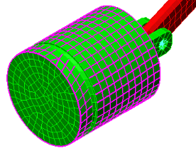
- Hold down the Ctrl key and click the remaining outside diameter surface. The piston should appear as shown below.
- Click
 Setup Constraints General Constraint.
 - Activate the Tx and Tz check boxes. The piston will only be free to translate in the Y direction.
- Click OK.
- Right-click the Part 3 heading in the browser (tree view) and choose Select Subentities Surfaces. All the surfaces of Part 3 are now selected.
- Click Setup Constraints General Constraint.
- Activate the Tx check box.
- Click OK. The crank will be free to move only in the Y and Z directions. Though not absolutely necessary, this constraint will stabilize the crank by preventing any twisting or bending due to flexure of the joints and will make convergence of the solution a little easier.