Use the Mesh Mesh 3D Mesh Settings dialog box to mesh a CAD solid model in the FEA Editor environment. It sets the mesh settings for all the parts in the model. An identical screen appears when you specify the mesh settings for a single part in the model. (Select a part or multiple parts in the browser (tree view), right-click, and select CAD Mesh Options Part.)
Mesh type section
Note that the mesh type will default automatically to Solid when importing CAD solid data and to Plate/shell when importing CAD surface data. It is also possible to define the mesh type on a per-part basis, overriding the global setting. When importing a CAD assembly with a mixture of solid and surface parts, the global mesh type will be set automatically based on the most prevalent type of part—Solid for a majority of solid CAD parts and Plate/shell for a majority of surface CAD parts. The less prevalent mesh type will be defined on a per-part basis using part mesh settings as an override of the global settings.
- Solid: Selected parts are meshed with solid elements (brick or tetrahedral).
- Midplane: Select if the selected parts are solid parts but will be collapsed to the midplane of the solid parts. After creating the midplane mesh, the average thickness of the plate elements is automatically used as the thickness for each surface. To use a specific value (for either the entire part or different surfaces within the part), clear the Use mid-plane mesh thickness check box in the Element Definition screen for the part.
- Plate/shell: Select if the selected parts are surfaces for example, have no modeled thickness.
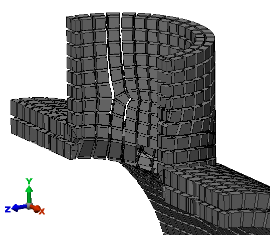
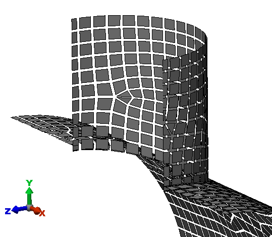
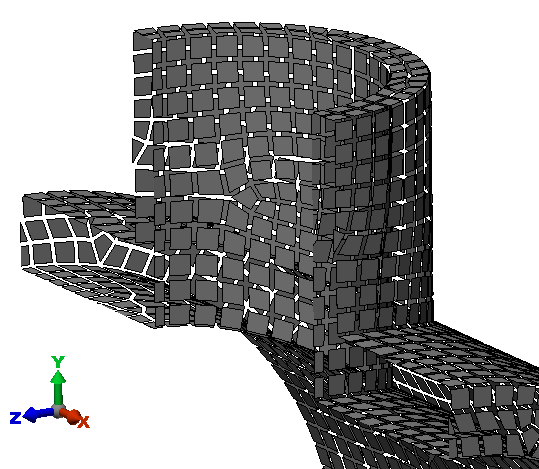
The difference between the three types of mesh (solid, midplane, and plate/shell) are demonstrated in the following images of two intersecting pipes. The figures show the model sliced in half, and the elements are shrunk to reveal the elements.
- Options: You can specify further mesh settings for the selected parts.
Examples of Each Mesh Type
The examples that follow demonstrate the difference in meshing behavior for the three mesh type settings based on the same CAD part data in all three cases.
Solid mesh: The volume between the inside surface and the outside surface of the CAD model is filled with brick elements. The thickness does not need to be entered. It is based on the mesh.
Midplane mesh: The inside surface and the outside surface of the CAD model are collapsed to the midplane location, and the mesh is created at the midplane. The thickness of the solid is represented by entering a numerical value (in the Element Definition) for the thickness of the elements. (The elements can be any type of area elements, such as plate elements or membrane elements.)
Plate/shell mesh: All surfaces of the CAD model, the inside surface and the outside surface, are meshed. The thickness of each element is represented by entering a numerical value (in the Element Definition). Unless you intended to create a double-walled vessel, this type of mesh is incorrect for this example CAD model. In this analysis, the two surfaces can move independently and pass through each other.
Control the mesh size
This slider in the Mesh size section controls the size of the mesh on the selected parts relative to the default size which is calculated based on the model dimensions.
Defaults button
Access the Meshing Option Defaults dialog box.
Mesh model button
The model is meshed with the current settings. This button will only be available if you are specifying the settings for the entire model.