When the Options button is pressed on the Model Mesh Settings screen or Part Mesh Settings screen and the Solid icon is selected, a screen with multiple tabs will appear. (Note: The Solid icon will only be present if the Solid radio button is selected in the Mesh type section of the Model Mesh Settings screen.) Click the link for the subject that you need more information about.
Select a mesh type
The mesh types can be selected in the Solid mesh type section of the General tab. The options are as follows:
- Bricks and tetrahedra: The solid mesh will consist of as many 8-node brick elements as possible with respect to the mesh size. When necessary toward the center of the model, 6-node wedge, 5-node pyramid or 4-mode tetrahedral elements may be created. The majority of the volume will consist of 8-node elements. This option will create the highest quality mesh with the fewest elements.
- All tetrahedra: The solid mesh will consist of all 4-node tetrahedral elements. The main purpose of this mesh type is for fluid flow analysis. If not using the boundary layer mesh described below, then the mesh should be an all tetrahedra mesh for fluid flow and multiphysics analyses. (Multiphysics analysis uses the All tetrahedra mesh type for all parts so that the faces match between the fluid parts and the solid parts.) (Technically, an all brick mesh would be required if using the Penalty formulation. But since the Penalty formulation is optimal only for very small model sizes, it is rarely encountered with a mesh derived from a CAD solid model.) For other analysis types, this option will require significantly more elements to get the same accuracy as the Bricks and tetrahedra option.
- Tetrahedra and wedges (boundary layer): A special mesh of boundary layer elements will be created at all surfaces of the part using 6-node wedge elements. Then, the solid mesh will consist of 4-node tetrahedral elements. This type of mesh is often used for fluid flow models but may also be suitable for other analyses where result gradients are steep in the regions near part surfaces.
- Bricks and wedges (layered mesh of thin parts): This mesh will create a user-entered number of solid elements through the thickness. Since the number through the thickness is applied throughout the part, this option is suitable for thin parts with relatively constant thickness. Note that although thin part meshing of multiple part assemblies is possible, the mesh may not be matched on parts that are in contact. A midplane mesh may be a viable option in this case.
The type of solid mesh selected will control what additional tabs are available. The options on these tabs are described in the sections below.
Aspect ratio
When available, the aspect ratio of the solid elements can be controlled using the Maximum aspect ratio section in the Quality tab. If the Automatic enforcement radio button is selected, an aspect ratio will be calculated based on the surface mesh. You can control the relative magnitude of this value using the slider. The smaller aspect ratio will result in better accuracy. This option will create the highest quality mesh with the lowest aspect ratio. If the Upper limit radio button is selected, a maximum aspect ratio will be specified in the adjacent field. No solid elements will be created with an aspect ratio exceeding this value. If the None radio button is selected, no restrictions will be applied to the aspect ratios of the elements.
Warp angle
When the Quality tab is available and the Include maximum warp angle constraint check box is activated, the warp angle of every internal face of the solid elements will be constrained to be less than the value specified in the adjacent field.
Volume-to-length ratio
When the Quality tab is available and the Include maximum volume-to-length ratio check box is activated, the ratio of the cube root of the volume of an element to the length of the longest edge will be constrained to be less than the value specified in the adjacent field.
Microholes
The Options tab is available and the Allow microholes check box in the Method section is activated. The solid mesh is created with high quality elements. The parameters that will be considered during the creation of the high quality elements include aspect ratio, collapse ratio, edge angle, twist, taper angle, skew angle and warp angle. Towards the center of the part, small voids, or microholes, may remain to facilitate the proliferation of higher quality elements. The microholes will be very small relative to the volume of the part and will be located as far from the surface of the part as possible to minimize the effect on the areas where a high stress is expected.
If you have run an analysis on a part with the NASTRAN processor and received warnings referring to the element quality, activating this option and regenerating the solid mesh may eliminate these warnings.
For models with complex geometric features, activating this option may result in shorter solid meshing times. For more information on microholes, see The Effects of Microholes within a Solid Mesh.
Mesh thin parts
There are two means of meshing thin-walled parts.
Thin cross-section schemes
If the Solid mesh type on the General tab is set to Bricks and wedges (layered mesh of thin parts), the Options tab is available. When the Use thin cross-section scheme check box is activated, the surface meshes may be altered in areas of small thickness so that the meshes are aligned. This will allow a solid mesh to be created with relatively uniform elements. It accomplishes this by adjusting the mesh on one of the surface if necessary to better match the opposite surface. If you want the surface mesh of a certain area to be maintained, specify the layer number of that area in the Do not change surface mesh of layer number field. This is useful if one side of the part has been matched to another part in the assembly.
Layered meshes
If the Solid mesh type on the General tab is set to Bricks and wedges (layered mesh of thin parts), the Layered Mesh tab is available. This method of meshing a thin-walled part is better since you can control how many elements are generated through the thickness. It accomplishes this by creating a midplane mesh on the part, and then extruding the midplane the number of elements specified to recreate the volume. There are two requirements for this type of meshing:
- Each region of the part must be uniform in thickness. Different regions can be different thickness. For example, a wedge shaped region will be meshed as if it were uniform in thickness and the average thickness.
- Although thin part meshing of multiple part assemblies is possible, the mesh may not be matched on parts that are in contact. A midplane mesh may be a viable option in this case.
The number of elements through the thickness is set with the Layers field on the Layered Mesh tab.
The thickness of the layered mesh is a constant within a region (defined by the surface numbers in the model). By default, the extruded layered mesh is equal to the average thickness of the part in that region. Use the User-specified maximum thickness field to set a limit on the thickness of a part in the calculation of the average thickness. Any regions thicker than the user-specified thickness will be set to the maximum thickness. Regions thinner than the maximum thickness are not affected.
Control properties of tetrahedral meshes
When the Tetrahedra tab is available, you can control the size of the tetrahedral elements in the Tetrahedral meshing options section. The size of the tetrahedral elements will be controlled by the Target edge length based on drop-down box. If the Fraction of mesh size option is selected, the value in the Target edge length field will be multiplied by the surface mesh size. If the Absolute mesh dimension option is selected, the value in the Target edge length field will be used You can control how the mesh size transitions from smaller areas of the model to larger areas using the Transition rate field. The value in this field will be the ratio of the average edge length of adjacent elements. This value must be greater than 1. Larger values will result in lower quality elements. An upper limit to the aspect ratio of the elements can be defined using the Quality field.
Control boundary layer meshes
When creating a mesh for a fluid part or fluid flow model, it is advantageous to have a thin layer of elements at the walls of the parts. Such a mesh helps calculate accurate behavior in the boundary layer, where fluid velocity gradients are greatest. If you plan on exporting your mesh to another FEA program for performing a fluid flow analysis, you may wish to produce a boundary layer mesh.
It is also conceivable that result gradients could be steep in near-surface regions for other analysis types. Here again, thin boundary layers could be used to improve the accuracy of the results in such regions.
To produce a boundary layer mesh, set the type of solid mesh to Tetrahedra and wedges (boundary layer). (If not using the boundary layer mesh, the all tetrahedra mesh is next recommended for fluid flow models. See Selecting a Mesh Type above.)
By default, this option produces a boundary layer mesh on all surfaces. This thin layer of elements can create convergence problems in a fluid flow analysis if the fluid is passing normal to the layer of thin elements and then entering into normal size elements. This condition occurs at the following locations in a model:
- Fluid inlet and outlet faces
- Faces with a fan or prescribed velocity
- Bonded faces between parts of an assembly.
In these situations, select the faces where a boundary layer mesh is NOT desired, right-click, and choose Exclude From Boundary Layer. That is, the boundary layer mesh should only be created at real walls. See the following figures, which depict the cross-section of a mesh inside a pipe.
| Inlet |
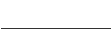 |
Outlet |
| Inlet |
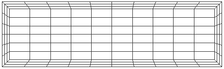 |
Outlet |
| Inlet |
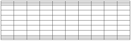 |
Outlet |
There is one exception to the use of the Exclude From Boundary Layer option at bonded surfaces between fluid parts. When the model includes multiple rotating frames of reference (specific to fluid flow analysis), it is beneficial to have uniform elements at the junction between the rotating frame and the stationary frame. This is a bonded face, but the boundary layer mesh is ideal for creating these uniform elements.
If the Tetrahedra and wedges (boundary layer) radio button is selected in the General tab, the Tetrahedra tab will be available. The boundary layer mesh can be controlled using the Boundary layer options section. The size of the elements in the boundary layers will be controlled by the Extrusion distance based on drop-down box. If the Fraction of mesh size option is selected, the value in the Total extrusion distance field will be multiplied by the surface mesh size. If the Absolute length dimension option is selected, the value in the Total extrusion distance field will be used If the Percentage average local size option is selected, the value in the Total extrusion distance field will be used as a percentage of the mesh size in the area of the boundary layer. You can control how the mesh size increases in adjacent boundary layers using the Growth rate field. The value in this field will be the ratio of the average edge length of elements in adjacent layers. This value must be greater than 1. You must specify how many boundary layers you want to be generated in the Layers drop-down box.
Use advanced meshing options
Activating the Provide detailed status information check box in the Advanced tab will output detailed meshing information to a log file. This information may be useful in determining why a mesh has failed.
During the solid meshing process, errors may be found in the surface mesh. If the Fix errors and continue solid meshing option is selected in the Connectivity voids check drop-down box on the Advanced tab, the mesher will attempt to correct the surface mesh. If the Do not fix errors option is selected, the mesher will stop. The surface mesh must be corrected before the solid mesh will be created.
If the Disable self-intersection check box on the Advanced tab is activated, the solid mesh process will not check to determine if the surface mesh intersects itself. This check box should only be activated after an original solid mesh has been generated on the model.
If the Attempt completion with errors check box on the Advanced tab is activated, a solid mesh will be generated regardless of errors in the surface mesh. This may result in voids throughout the model. If this check box is activated, you should be sure to verify the solid mesh.
Mesh a gasket
Any part destined to be defined as gasket elements needs to have a mesh with only one element through the thickness. This is accomplished in a CAD solid model by assigning the part to a Gasket solid mesh with one of these methods:
- Set the element type for the part to 3D Gasket.
- Right-click the part in the display area or the tree view and select the CAD Mesh Options
 Part command. Then with the Mesh type set to Solid, click the Options button, choose the Solid button, and set the solid mesh type to Gasket.