Gaskets are widely used in many assemblies and play essential roles in sealing and transferring force. While some gaskets have simple geometry and material components, most are made of complicated structure and material components. They exhibit complicated and highly nonlinear behavior under compressive loading and unloading. It is usually not practical to model gaskets according to their exact geometry and material components. In reality, it is the mechanical response of gaskets that matters most. Therefore, a special gasket element can be designated to simulate the gasket behavior and to avoid fine details of gasket itself.
The gasket element behavior is unique in the following areas:
- Only compressive stresses through the thickness are developed and transmitted. Normal stresses. Stresses and forces in the plane of the gasket are ignored. So even though the gasket part may be bonded to the mating part (by virtue of using the same nodes on each part), the connection is better thought of as a 0 friction surface since no shear forces are developed in the gasket.
- The mesh must be created with just one element through the thickness.
- In some situations, the user needs to indicate which surfaces are the top and the bottom. This occurs when the thickness dimension (in the compression direction) of the gasket is larger than the width (normal to the compression direction). See below.
- The material properties are specific to a given thickness of gasket.
2D gasket elements can be isoparametric quadrilaterals (4 nodes) or triangular (3 nodes) elements.
These elements are confined to the global YZ plane. The element can represent either planar (plane strain condition) or axisymmetric conditions. In both cases, each element node has two translational degrees of freedom (in Y and Z directions).
The material model of the gasket element includes the capability of a multi-linear elastic curve, a yield point, multi-linear plastic curve, and multiple unloading curves, each of which is defined by multi-linear curves.
Applying Loads to the Surface:
Uniform pressure, traction, and hydrostatic pressure can be applied only to the top face or bottom face of the 2D gasket element, but not to both. Pressure is applied by changing the surface number attribute of the line, and then applying a pressure to the surface. The pressure assigned to the face with the higher surface number is the face of the element that receives the pressure.
Select Types of 2D Gasket Elements
There are two types of 2D gasket elements available for a nonlinear analysis. These can be selected in the Geometry Type drop-down box in the Element Definition dialog.
- Axisymmetric: Select this geometry type for elements that model solids with geometric, load and boundary condition symmetry about the Z axis. Negative Y coordinates are not admissible. If a node lies along the axis of revolution (the Z axis) the translation in the Y direction must be constrained. Nodal loads are normalized by the number of radians in a circle (load divided by radians).
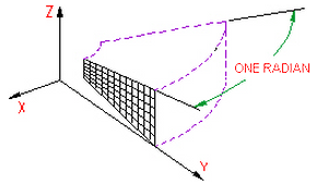
Figure 1: 2D Axisymmetric Model
- Plane Strain: Select this geometry type to model planar solids. A thickness of 1 unit is assumed; the setup of other parts in the model may need to be set appropriately to account for the gasket thickness. A thickness can be entered using the Thickness (visualization only) field, but this thickness is only used for the 3D visualization in the Results environment. (See the Browser Functions page.) All input loads and results are based on the 1 unit thickness.
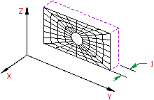
Figure 2: 2D Plane Strain
Advanced 2D Gasket Element Parameters
The other parameters on the Element Definition dialog determine the behavior of the gasket during the analysis.
- Analysis Formulation pull-down determines if large deflection effects are included in the analysis. If Geometrically nonlinear is chosen, the changing thickness and orientation of the gasket is based on the current gasket deformation. Large deflection effects due to geometry changes are included. If Linear is chosen, the thickness and orientation are calculated from the original position. Small deflections effects are assumed and effects due to the geometry changes are ignored.
- Integration Order pull-down sets the accuracy of the calculation across the element. For rectangular shaped elements, select the 2nd Order option. For moderately distorted elements, select the 3rd Order option. For extremely distorted elements, select the 4th Order option. The computation time for element stiffness formulation increases as the third power of the integration order. Consequently, the lowest integration order which produces acceptable results should be used to reduce processing time.
- Stabilization Factor field provides numerical stability for models. Since the gasket only has stiffness in the thickness direction, motion perpendicular to the thickness can be unstable, especially if performing a static stress analysis and if the parts connected through the gasket are not restrained by other means (bolts connecting the parts, boundary conditions, and so on). The Stabilization Factor can be zero when the gasket is well constrained. The stiffness added by the Stabilization Factor is the product of the stabilization factor and the stiffness of the last segment of the gasket material property curve. Since this is added stiffness to the diagonal terms of the elasticity matrix, it should be sufficiently small so that it will not affect the convergence and accuracy of the results.
- Use default initial thickness direction throughout check box is available only if the Analysis Formulation is set to Linear. When activated, the thickness of the gasket is set to a constant thickness specified by the Scalar Y and Scalar Z inputs. This can be beneficial for very thin gaskets where the numerical error in the nodal coordinates can have a significant effect on the thickness.
Basic Steps for Use of 2D Gasket Elements
- Be sure that a unit system is defined.
- Be sure that the model is using a nonlinear analysis type.
- When creating the mesh of the gasket, use one element through the thickness.
- Right-click the Element Type heading for the part that you want to be 2D gasket elements. Tip: Useful commands for converting 3D models to 2D models are Draw
 Pattern Relocate & Scale, Draw Pattern Rotate or Copy, and Draw Modify Project to Plane. For example, you may accidentally create a mesh in the XY plane. You can rotate the mesh to the YZ plane using either the Relocate & Scale or Rotate command. Due to round-off, some nodes may have a small X coordinate value that prevents the element type from being set to 2D. In this case, use Project to Plane to snap the nodes exactly to the YZ plane.
 - Select the 2D Gasket command.
- Right-click the Element Definition heading.
- Select the Edit Element Definition command.
- Specify the appropriate input in the Element Definition dialog to specify the geometry and solution parameters for the gasket element.
- Press the OK button.
- Right-click the Material heading for the part and choose Edit Material. Enter the material properties for the gasket.
- Select the surface or surfaces that define the top face and bottom face of the gasket. This can be done in the display area (Selection Select Surfaces) or in the Surfaces branch of the tree view. (The two faces can be on the same surface number or different surface numbers.) Right-click and choose Gasket's Top/Bottom Surface. The lines on the sides of the gasket that connect the top and bottom faces should not be on the same surface number as the top or bottom surface.