We will now create a joint between the piston and the arm to allow the parts to rotate about the centerline of the joint.
- Click
 View
View  Navigate Orientation Right View.
 - Use
 View Navigate Zoom Window to zoom in on the area where the piston and arm meet.
 - With
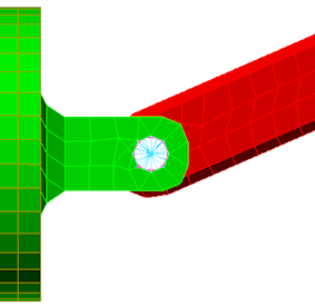
 Selection Shape Circle and
  Selection Select Surfaces active, draw a circle enclosing the hole where the piston and arm meet, as shown in the following image.
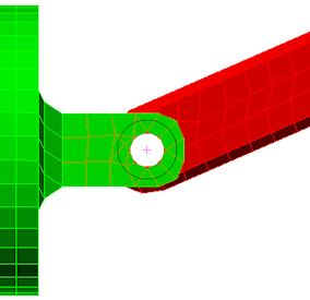
- Click
 Mesh CAD Additions Joint. The Create Joint dialog box displays. The three selected surfaces (two holes in the piston and one in the arm) are listed under the Participating surfaces heading. The joint type is shown as the default Pin Joint (lines to axis endpoints). Note: It is also possible to add surfaces to the Participating surfaces list by selecting them and clicking Add after starting the Create Joint command.
Click OK to add the pin joint, which will appear as shown in the following image.