- Click the heading for Part 3 in the browser (tree view) to select the crank. Then, click
 View
View  Navigate Zoom Selected (or the equivalent Navigation Bar command) to tightly enclose the crank within the display area. It does not matter if the crank is off-screen when it is selected.
 - With the
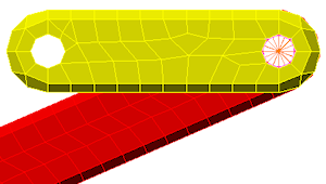
 Selection Shape Circle and
  Selection Select Surfaces commands still active, draw a circle enclosing the hole where the arm and crank meet, as shown in the following image.
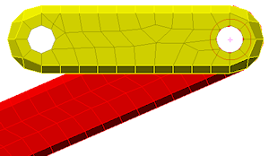
- Select
 Mesh CAD Additions Joint and click OK to add the pin joint, which appears as shown in the following image.