Now we will apply the four 250 lbf forces in the -Z direction to the top of the model.
- Select
 View
View  Navigate Orientation Front View.
 - With the
 Selection Shape Point or Rectangle and
  Selection Select Vertices commands active, click and drag to draw a box enclosing the top of the model as shown below.
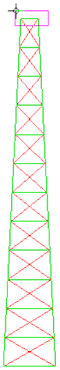
- Click
 Setup Loads Force.
 - Type -125 in the Magnitude field. The title bar indicates, "Creating 8 Nodal Force Objects." Each of the selected nodes is at the intersection of Parts 1 and 2. There are two nodes at each corner, one for each part, and the specified force will be applied to each node. Therefore, we must divide the 250 lbf load in half.
- Select the Z radio button.
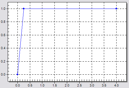
- Click the Curve button. The Multiplier Table Editor dialog box displays to define a load curve.
- Click Add Row twice for a total of three rows in the table.
- Type 0.25 in the second row of the Time column.
- Type 1 in the second row of the Multiplier column.
- Type 4 in the third row of the Time column.
- Type 1 in the third row of the Multiplier column.
- Press Enter. The load curve should appear within the dialog as shown below.
- Click OK to accept the load curve.
- Click Add Row twice for a total of three rows in the table.
- Click OK to apply the forces.