Abstract
The accuracy of finite element analysis (FEA) of solid models generally benefits from meshes composed of elements of high geometric quality. Autodesk Simulation has developed an automated solid meshing method that enforces strict geometry checks used by NASTRAN processors. This automatic generation of solid elements can result in meshes with small internal voids. Generally, such voids will only occur when considering parts with complex shapes, including CAD solid models. In this paper, we consider results obtained with meshes that contain such voids. The automatic meshing method is optimized to minimize the size of these voids, thus the term microholes. These results are compared with others obtained using fully filled parts, as well as with analytical solutions. We demonstrate how models with microholes and those with fully filled meshes both result in insignificantly different results.
Introduction
The application of FEA to 3D solid models requires the generation of meshes composed solely of tetrahedral elements or of a hybrid combination of bricks, wedges, pyramids and tetrahedra. The latter approach is preferred when considering solids whose surface is represented using quadrilaterals, and can be further refined to avoid the generation of pyramids. Proper mesh generation attempts to build the best quality elements for codes like NASTRAN. In general, automatic mesh generators aim to produce elements with low aspect ratios. Autodesk Simulation’s automatic solid mesh generators not only minimize aspect ratio, but build elements adhering to the geometry checks utilized by NASTRAN processors. These geometric checks include: aspect ratio, collapse ratio, taper ratio, interior angle, skew angle, twist angle, and warp factor.
It is desirable to completely fill a solid with a mesh composed solely of elements adhering to high-quality criteria, such as those discussed above. One would expect that such a mesh would produce highly accurate FEA results. The problem is that obtaining such a mesh is not always possible for models with complex geometry. This is primarily because detailed geometric features constrain the mesh generator so as to prevent the creation of meshes with gradual transitions between small and large element sizes. The advent of CAD has made models with detailed features commonplace. If you utilize a mesh size comparable or smaller than the feature size, then transitions are not needed, and the high-quality constraints can be enforced throughout fully filled parts. Nevertheless, this approach requires extremely small mesh sizes, which produces models with an unpractical number of elements, whose solution requires unreasonable computing resources. After all, the goal of the engineer is usually to maximize accuracy, while maintaining a practical approach.
In an attempt to avoid the impractical requirement of extremely fine meshes to satisfy both the filled solid and high element quality constraints, we have developed an automatic meshing method that leaves insignificantly sized voids - within the solid. The primary goal of this scheme is to provide the highest accuracy possible by building only elements adhering to strict geometric quality. We have developed another automatic meshing method that completely fills the parts by first applying the high-quality meshing method that results in microholes, and then fills the small voids with elements that may not necessarily adhere to the geometry checks. As we will show, neither the meshes with microholes, nor the full meshes with a few elements violating the geometry checks, result in significant accuracy losses. After all, the latter type of mesh can certainly be viewed as an improvement over common automatically generated FEA meshes. Such meshes can have numerous poor quality elements, occupying large portions of the overall volume.
Both meshing methods discussed above address this concern by building elements using a marching algorithm from the surface inward. This approach usually produces elements adhering to the strict geometry checks near the surface, and only produces microholes or lower-quality elements deep within the parts. It is desirable for the sake of accuracy to have the best quality elements near the surface, where usually the greatest gradients in FEA solutions usually occur. This is because in most FEA applications, including stress analysis, the loads and constraints as well as part-to-part interactions generally occur on the surface.
In this paper, we show how the existence of microholes can produce noticeably more accurate FEA results over comparable models with fully filled meshes. Results were obtained for analysis types based on Lagrangian formulations, which include stress, thermal and electrostatics. Models with microholes are not appropriate for Eulerian formulations, such as fluid flow analysis.
Comparison Study
The effect of microholes on an FEA solution is examined by comparing results of models with and without microholes. Specifically, we compare results of identical surface meshes whose solid meshes were obtained using the two different meshing methods. To focus on the effect of microholes, and not on mesh type, we consider only meshes using Autodesk Simulation’s hybrid solid mesh types. In either the tetrahedral or the hybrid solid mesh types, microholes occur when tetrahedral elements cannot be built to fill a given small void. In both meshing methods the tetrahedral elements are generated only in the final meshing stages. The models considered in this study may at first appear to have relatively simple geometry, lacking the small features known to be the cause of microholes. Nevertheless, because localized mesh refinement was utilized, the resulting abrupt transitions in the surface mesh size prompted the production of microholes. It should be noted that all of the models presented in this paper contain typical to large microhole volume fractions, thus maximizing their effect.
Figure 1 depicts the surface geometry of a three-part CAD assembly. This surface mesh resulted in a relatively large 0.00207 microhole volume fraction. Static Stress with Linear Material Models and Natural Frequency (Modal) analyses were conducted on this model, and on its fully filled counterpart. Figure 2 shows how similar stress results are obtained for both versions of the model. The modal analysis was utilized to obtain the first five natural frequencies, and, as Table 1 shows, both versions of the model again gave solutions with insignificant engineering differences.
Figure 1: FEA model, including mesh, of a three-part assembly of a circular rod bonded to two brackets, which are fixed using boundary conditions on the edges of the holes located on their flat ends (red triangles on the underside). In the Static Stress with Linear Material Models analysis, a surface force of 5.0 x 10⁸ dynes is applied on one end of the rod (yellow arrows).
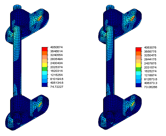
Figure 2: von Mises stress distributions obtained from the Static Stress with Linear Material Models analysis of a three-part assembly of a circular rod bonded to two brackets. The figure on the left is for the model without microholes, whereas that on the right is for the model with microholes. The latter predicts a maximum stress 0.31% greater than the former.
|
Mode number, n |
Models without Microholes |
Models with Microholes |
Percent difference (%) |
|
1 |
1132.8 Hz |
1129.2 Hz |
0.318 |
|
2 |
1169.9 Hz |
1168.1 Hz |
0.154 |
|
3 |
1228.1 Hz |
1226.1 Hz |
0.163 |
|
4 |
2877.4 Hz |
2875.0 Hz |
0.083 |
|
5 |
3007.0 Hz |
3003.2 Hz |
0.126 |
|
Table 1: Modal frequencies obtained from Natural Frequency (Modal) analysis of a three-part assembly of a circular rod bonded to two brackets. Note how all these frequencies compare to within 0.32%. |
|||
Figure 3 depicts the Steady-State Heat Transfer results of a single-part model of a ring with and without microholes. The microholes resulted in a more typical 0.00046 volume fraction. As in the Static Stress with Linear Material Models analysis, both versions of the model produced highly similar results. Figure 4 depicts displacement results obtained using Autodesk Simulation’s Mechanical Event Simulation (MES) software for the two versions of the ring model. Even for nonlinear FEA, the presence of microholes did not significantly affect the results. Finally, Figure 5 depicts voltage results obtained using Autodesk Simulation’s Electrostatic Current and Voltage analysis for the two versions of the model. As expected because of the underlying similarities between electrostatic and thermal analysis, the presence of microholes had little effect on the results.
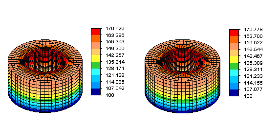
Figure 3: Temperature distributions obtained from a Steady-State Heat Transfer analysis for ring model with the base maintained at 100 °F, and a heat flux of 0.642 BTU / (sec . in2) applied to the inner surface. The figure on the left is for the model without microholes, whereas that on the right is for the model with microholes. The latter predicts a maximum temperature 0.349 °F greater than the former.
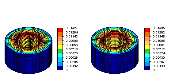
Figure 4: Displacement magnitude distributions obtained from a Mechanical Event Simulation (MES) analysis for a ring model with the outer surface fixed and a time-proportional pressure reaching a maximum of 100 lb/in2 seconds applied on the inner surface. The results are at the end of a 0.1 second event. The figure on the left is for the model without microholes, whereas that on the right is for the model with microholes. The latter predicts a maximum nodal displacement 0.56% greater than the former.
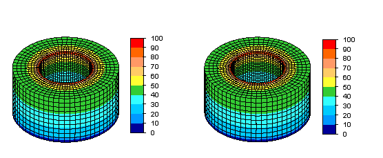
Figure 5: Voltage distributions obtained from Electrostatic Current and Voltage analysis for ring model with a voltage of 100 V applied on the inner edge of top surface, and 0 V applied on the outer edge of the outer surface. The figure on the left is for the model without microholes, whereas that on the right is for the model with microholes. A comparison of the maximum voltage on the outer top edge shows a difference of 0.02% between the two models.
Conclusions
A new automatic meshing method with emphasis on accuracy has been developed. This method only generates elements of high geometric quality, yet leaves microholes. This meshing method has been extended to fill these small voids with elements that may not satisfy high geometric quality constraints. Both methods generate meshes capable of producing highly accurate FEA results. Several examples demonstrated how FEA models with typical to large volume fractions of microholes and those with fully filled meshes produced results of equal engineering accuracy.