Given: A stainless steel cylinder (AISI 304) initially at 600 K is quenched by submersion in an oil bath maintained at 300 K with a convection of h = 500 W/m 2 K. The length of the cylinder is 60 mm and the diameter is 80 mm. Material properties for stainless steel (AISI 304), taken from Introduction to Heat Transfer, are: density = 7900 kg/m 3 , conduction coefficient = 17.4 W/m K, and specific heat = 526 J/kg K.
Find: What are the temperatures at the center of the cylinder, at the center of a circular face, and at the midheight of the side at 3 minutes into the cooling process?
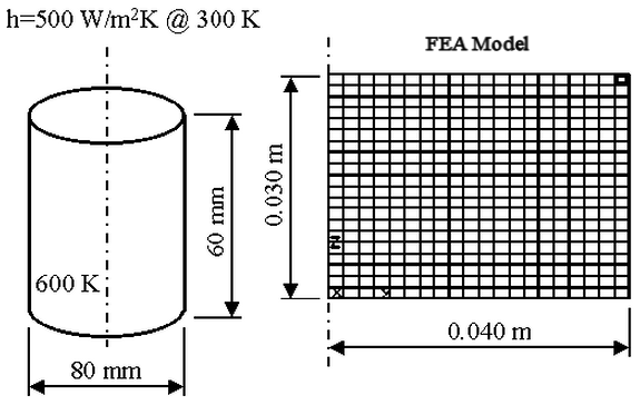
Figure 1: Problem Geometry
This example only covers creating the model. For instructions on setting up and performing the analysis, see Cylinder with Convection. We will create two separate Design Scenarios within one model: one design scenario is 2D axisymmetric elements, and one Design Scenario is brick elements.
Method 1: 2D Axisymmetric Model
For an axisymmetric model, only the cross-section from the center line of the cylinder to the outside is modeled. Due to vertical symmetry, only the top half of the cross-section is modeled. The model must be located in the YZ plane with the Z axis the centerline.
- Start a new FEA model.
- Set the analysis type to Thermal: Transient Heat Transfer.
- The analysis uses the Metric mks (SI) unit system but using Kelvin for temperature units. Click Override Default Units and select Metric mks (SI) form the Unit System drop-down list. This sets everything we want except for the temperature. Change the Unit System to Custom and set the Temperature (Absolute) to K (K). Click OK to set the units.
- Click New and enter a model name.
- Use Mesh
 Structured Mesh 4 Point Rectangular to create a structured mesh.
 - Set Part and Surface to 1. Type 20 in the AB field. Type 20 in the BC field. Define Point A as (0,0,0), Point B as (0,0.040,0), Point C as (0,0.040,0.030) and Point D as (0,0,0.030). Click Apply to create the mesh.
- Click the X button to close the Point Mesh Setup dialog box.
- To see what was created, change the view with View Navigate Orientation Right View.
- The outside of the cylinder has a convection load. Use Selection Shape Rectangle and Selection Select Lines to select the lines along the top and right edges of the model. (When selecting the second edge, hold the Shift key to add to the first selection.) Use Draw Modify Attributes to place the lines in Surface 2. Click OK.
Method 2: 3D Brick Model
The 2D model can be easily converted into a 3D brick model. It works better to convert it after performing the analysis on the 2D model. There is no need to enter the analysis parameters twice. They are copied from Design Scenario 1 to Design Scenario 2.