Now we will create the small circle in a new plane that is 16 inches below the XY plane. We will divide the circle into two arcs and orient them so that we can create the structured meshes.
- Right-click the Planes heading in the browser (tree view) and select New Plane.
- Select XY in the Plane drop-down list.
- Select the Use Offset check box.
- Type -16 in the distance input field below Use Offset.
- Click OK to create a plane parallel to the XY plane at Z = -16 inches.
- Right-click the Plane 4 heading in the browser and select Sketch.
- Click
 Draw
Draw  Draw Circle Center and Radius. Then...
 - To specify the point (-10, 0, -16) as the center, type -10 in the X: field and press Enter. Since we are sketching in the Z = -16 plane, all the Z coordinates are set automatically to -16, regardless of what we specify.
- To specify the point (-5, 0, -16) as a point on the circle, type -5 in the X: field and press Enter.
- Click Apply.
- Press Esc to exit the circle command.
- With the
 Selection Shape Point or Rectangle and
  Selection Select Construction Objects commands active, click the circle to select it.
 - Click
 Draw Modify Divide and click OK to split the circle into two arcs.
 - Click and drag to draw a selection rectangle enclosing the circle, to select both of the small arcs.
- Click
 Draw Pattern Rotate or Copy.
 - Type 90 in the Total angle field and select the DZ radio button in the "Rotation Axis" section of the dialog box.
- Click Select Center Point and click the construction vertex at the center of the small circle.
- Click OK. The two arcs are now oriented in the same way as the large arc and straight line. This is necessary to build the correct structured meshes between these construction objects.
- Right-click the Plane 4 heading in the browser and deselect Sketch to exit the sketch mode.
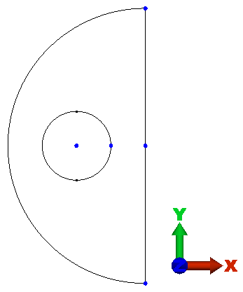
The model should now display as shown in the following image.