What are Brick Elements?
Three-dimensional thermal brick elements are 4-, 5-, 6- and 8-node elements formulated in 3D space. The determination of how many nodes comprise a given element is done automatically based on the connectivity of the lines. You do not need to do anything to designate how many nodes will be on the element. A model made of 3D bricks can contain a mix of 4-, 5-, 6- and 8- node bricks.
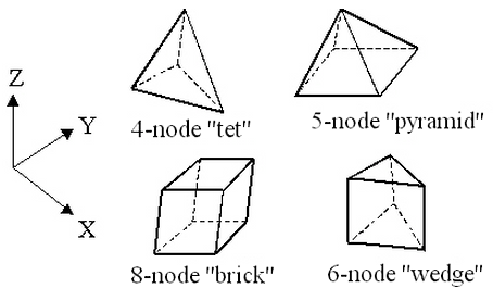
Figure 1: Brick Elements
Heat flows in all three directions, and therefore a three-dimensional temperature distribution is calculated.
Only one degree-of-freedom is defined for these elements, the temperature. Temperature-dependent, orthotropic material properties can be defined.
Applying Surface Loads
When applying loads to a surface number of a brick part, be aware that some models may not have all the lines on the face to be loaded on the same surface number. What happens in this situation? If the model originated from a CAD solid model, all faces coincident with the surface of the CAD model will receive the load regardless of the surface number of the lines. In hand-built models and on CAD parts that are altered so that the part is no longer associated with the CAD part, the surface number that is common in any three of the four lines that define a face (four-node region) or two of the three lines (three-node region) determines the surface number of that face.
Brick Element Parameters
When using brick elements, you must specify the material model for this part in the Material Model drop-down box of the Element Definition dialog. The options available are as follows:
- Isotropic: If the material properties in all directions are identical, select the Isotropic option. These properties are also independent of temperature.
- Isotropic, phase change If the analysis type is Transient Heat Transfer, then the option Isotropic, phase change will be available. Use this material model when the part may change phase from solid to liquid (melting) or from liquid to solid (freezing). The material properties are independent of temperature.
- Isotropic, phase change, temperature dependent If the analysis type is Transient Heat Transfer, then the option Isotropic, phase change, temperature dependent will be available. Use this material model when the part may change phase from solid to liquid (melting) or from liquid to solid (freezing). The material properties in the solid phase and liquid phase are temperature dependent.
- Orthotropic: If the material properties vary along three orthogonal axes but not with temperature, select the Orthotropic option. If selected, you will be able to orient the material axes using the Orientation tab (see description below).
- Temperature Dependent Isotropic If the material properties are identical in all directions but change with temperature, select the Temperature Dependent Isotropic option.
- Temperature Dependent Orthotropic: If the material properties vary along three orthogonal axes and change with temperature, select the Temperature Dependent Orthotropic option. If selected, you will be able to orient the material axes using the Orientationtab (see description below). Tip:
- Material properties, as is required with all material models. See the page Setting Up and Performing the Analysis: Thermal: Material Properties: Isotropic Phase Change Material Properties.
- Initial temperatures. In addition to the normal requirement of setting the initial temperature for a transient heat transfer analysis, the initial state of the part with phase change solid, liquid, or some fraction in between is based on the initial temperature. Either apply initial temperatures to the part (see the page Setting Up and Performing the Analysis: Thermal: Loads and Constraints: Temperature) or assign a default global temperature (see the page Setting Up and Performing the Analysis: Thermal: Analysis Parameters: Transient Heat Transfer).
- Set the relationship used to determine the liquid fraction (see the paragraph Calculating the Liquid Fraction on the page Setting Up and Performing the Analysis: Thermal: Analysis Parameters: Transient Heat Transfer).
- An iterative process is used during the solution when a phase change material is included. The convergence tolerances may need to be smaller than you are accustomed to. See the paragraph Controlling the Nonlinear Iterations on the page Setting Up and Performing the Analysis: Thermal: Analysis Parameters: Transient Heat Transfer.
In addition to setting the material model to include the effects of phase change, the following items need to be set:
Note: Although a change in phase can be included in the transient heat transfer analysis, the motion of the fluid is not considered. For example, an ice cube will melt and change to water, but the water remains in the same location. There is no transport of heat due to buoyancy effects or motion of the fluid (for example, run-off) in a transient heat transfer analysis.
If you want the brick elements in this part to have the midside nodes activated, select the Included option in the Midside Nodes drop-down box. If this option is selected, the brick elements will have additional nodes defined at the midpoints of each edge. (For meshes of CAD solid models, the midside nodes follow the original curvature of the CAD surface, depending on the option selected before creating the mesh. For hand-built models and CAD model meshes that are altered, the midside node is located at the midpoint between the corner nodes.) This will change an 8-node brick element into a 20-node brick element. An element with midside nodes will result in more accurately calculated gradients. Elements with midside nodes increase processing time. If the mesh is sufficiently small, then midside nodes may not provide any significant increase in accuracy.
Next, select the integration order that will be used for the brick elements in this part in the Integration Order drop-down box. For rectangular shaped elements, select the 2nd Order option. For moderately distorted elements, select the 3rd Order option. For extremely distorted elements, select the 4th Order option. The computation time for element stiffness formulation increases as the third power of the integration order. Consequently, the lowest integration order which produces acceptable results should be used to reduce processing time.
Next, you must specify how the heat flow is calculated in the Heat Flow Calculation drop-down box. If the Projected at Centroid option is selected, the heat flux for this part will be calculated from the derived nodal temperatures using Fourier's law. If the Nonlinear Based on BC option is selected, the heat flux for exterior surfaces with convection or radiation loads on this part will be calculated using the input parameters of the convection or radiation boundary condition and the derived nodal temperatures. The heat flux for interior faces is not affected by this option. If the Linear Based on BC option is selected, the heat flux for exterior surfaces with convection or radiation loads on this part will be calculated using the same method as the Nonlinear Based on BC option except that the heat flux on surfaces with radiation loads will be linearized.
It is only necessary to use the Nonlinear Based on BC or Linear Based on BC options if the actual heat flux output for the radiation or convection boundary condition is desired. The actual heat flows are based on the surface fluxes. For an adequately refined finite element mesh, the heat fluxes at the surface should be equal for all selections.
If you want two or more other parts in this model to exchange heat through body-to-body radiation through this part, select the Transparent option in the Body-to-Body Radiation drop-down box. This is especially useful in a steady coupled fluid flow and thermal analysis where two solid parts radiate to each other through the fluid part.
Control Orientation of Brick Elements
If this part of brick elements is using an orthotropic material model, you will need to define the orientation of material axes 1, 2 and 3 in the Orientation tab of the Element Definition dialog.
The material axes for a brick element are the r, s and t axes. These axes will be defined by specifying three nodes in the Orientation Node 1, Orientation Node 2, and Orientation Node 3 fields. You must first check the model in the Results environment to determine the node numbers.
- The r axis is defined as the vector from Orientation Node 1 to Orientation Node 2.
- The s axis is perpendicular to the r axis; lies in the plane formed by nodes 1, 2, and 3; and is on the same side of the r vector as Orientation Node 3.
- The t axis is the cross product of the r and s axes.
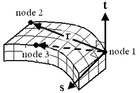
Figure 2: Orientation of the Material Axes
To Use Brick Elements
- Be sure that a units system is defined.
- Be sure that the model is using a thermal analysis type.
- Right-click the Element Type heading for the part that you want to be brick elements.
- Select the Brick command.
- Right-click the Element Definition heading.
- Select the Edit Element Definition command.
- Select the appropriate material model for this part in the Material Model drop-down box.
- If you selected the Orthotropic option in the Material Model drop-down box click the Orientation tab and specify the nodes to define the material axes.
- Press the OK button.