What Does Body-to-Body Radiation Do?
- Body-to-body radiation will account for the transfer of heat by radiation between multiple surfaces.
- The amount of heat transfer that occurs is related to the temperature difference between the two parts, the view factor between the two parts and the emissivity of the two surfaces.
Apply Body-to-Body Radiation
Body-to-body radiation can be applied in a heat transfer analysis by right-clicking anywhere in the display area except for on the model. In the menu, select the Body-to-Body Radiation command. Be sure that no objects are selected when you right-click, a menu displays for those objects. If the menu for the Body-to-Body Radiation command does not display, press <Esc> a few times to cancel all selections and right-click again.
Define Radiation Surfaces
Put the surfaces to be involved in the radiation on a unique surface number, namely, the highest surface number of any of the lines making the elements that radiate. To determine which of the six possible sides of a brick element are involved in the radiation, the solver checks the surface number of each line making an element. Each face that has a majority of these lines (3 of 4 sides, or 2 of 3 sides) on the highest surface number can be involved in the radiation. Faces whose lines are not on the highest surface number on the element cannot be involved in the radiation.
To set up body-to-body radiation, first define radiation surfaces. These radiation surfaces can be identical to the surfaces in your model or can be sets of surfaces in your model. Press the Define surfaces button. In the Body-to-Body Radiation Surfaces dialog, you will press the Add surface button to display the Part and Surface Selection dialog. Use the pull-downs to add an individual surface from your model into the radiation surface. If you add a surface from a plate element part, you will also need to specify if the top, bottom or both sides of the plate will be involved. The top of a plate element is opposite from the element normal point defined in the Element Definition dialog. Once the selection is made, click the OK button.
After defining the surface using the Part and Surface Selection dialog, you will need to specify if the emissivity of the surface is temperature independent or temperature dependent in the Type of emissivity drop-down box. If the Temperature independent option is selected, you must define the constant emissivity in the Temperature independent emissivity field. If the Temperature dependent option is selected, you must define the emissivity values at each temperature in a tabular format by pressing the Emissivity curves button. The emissivity values will be linearly interpolated between temperature values.
The Status pull-down is a convenient way to remove the radiation surface from the calculation without deleting all the input. The options are as follows:
- Enabled: the radiation surface will participate in the radiation calculation.
- Disabled: the radiation surface will not participate in the radiation calculation. The end result is the same as if the surface were deleted from the radiation setup. The advantage of disabling it is that the radiation surface can be enabled again at a later time without redefining the input.
- Enabled (Inactive) and Disabled (Inactive): You cannot set these options. If the part/surface number is removed from the model, such as the lines are deleted or changed to a different surface number, then the corresponding radiation surface is automatically set to inactive. This simply indicates that the radiation surface was defined previously but no longer exists in the model, and therefore will have no effect. If the part/surface number is returned to the model, then the Status will automatically be returned to the previous setting (either Enabled or Disabled).
When defining a radiation surface with the Part and Surface Selection dialog, one option is to choose All as the surface number. This will indicate that all free surfaces of the part are involved in body-to-body radiation. If all surfaces except for one surface are involved in the radiation, then a time-saving tip is to choose All on the Part and Surface Selection dialog, and then use the Surface avoided pull-down on the Body-to-Body Radiation Surfaces dialog to exclude one surface from the radiation surface.
Define Radiation Enclosures
Once the radiation surfaces are defined, you must place them into enclosures. Due to reflection between surfaces, body-to-body radiation must be defined differently than other types of surface interactions that you may be familiar with. Take surface-to-surface contact for example. Surface 2 may contact Surface 3, and independently contact Surface 4. This does not mean that Surfaces 3 and 4 may contact. In body-to-body radiation, if Surface 2 can radiate to Surface 3 and Surface 4, then Surfaces 3 and 4 can exchange radiation either directly or indirectly as shown in Figure 1.
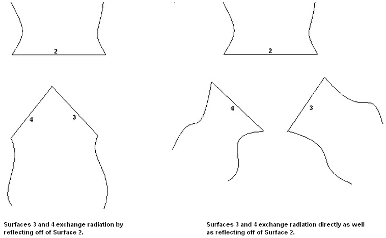
Figure 1. Surface 2, 3, and 4 (and the ambient) form one Enclosure: a set of Surfaces that radiate with each other but no other Surfaces
Consequently, all surfaces that see each other, directly or indirectly, form one enclosure. Figure 2 shows a model in which one enclosure would be defined. Figure 3 shows a model in which four enclosures would be defined
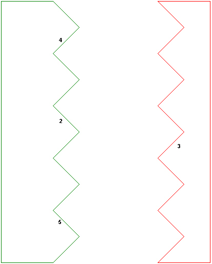
Figure 2. Regardless of how many surface numbers are used to define the serrations (4 are shown above), all must be defined as one enclosure. Mathematically, Surface 4 can radiate to Surface 5 through multiple reflections.
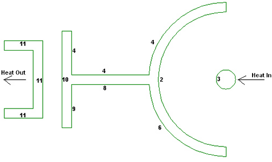
Figure 3. Four independent sets of Surfaces that radiate between each other exist. Thus, four enclosures would be defined. Enclosure 1: Surfaces 2 and 3; Enclosure 2: Surface 4; Enclosure 3: Surfaces 6, 8, and 9; and Enclosure 4: Surfaces 10 and 11
You can add radiation surfaces to an enclosure by pressing the Add button in the Surfaces section.
If the view factors do not sum to 1 in the enclosure (a totally enclosed volume), the enclosure will also radiate to the ambient conditions. Even with a totally enclosed volume, it is unlikely that mathematically the view factor will sum to 1. Thus, the rest of the radiation goes to a source that must be specified by selecting the Time-independent or Time-dependent option in the Ambient temperature drop-down box. If the Time-independent option is selected, define the constant ambient temperature in the Ambient temperature value field. If you are performing a transient heat transfer analysis and the Time-dependent option is selected, specify the load curve that the ambient temperature will follow in the Ambient temperature load curve drop-down box.
If the enclosure must take shadowing into account, select the Included option in the Shadowing drop-down box. Shadowing indicates that one body blocks the direct line-of-sight between surfaces of another body. The classic example is nested cylinders (see Figure 4). Mathematically, the inside of the large cylinder (Surface 2) could radiate across the diameter, passing right through Surface 3. To avoid this situation, shadowing should be included. (Only surfaces defined in the enclosure will have a shadowing effect). The enclosure in Figure 2 would also need shadowing Included to prevent radiation from (mathematically) passing through the body.
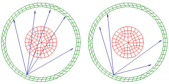
(a) (b)
Figure 4. Without shadowing, (a), a point on the inside of the pipe can see all other points on inside of the pipe. With shadowing (b), part of the view is blocked by the inner cylinder.
Define Body-to-Body Radiation Parameters
The Parameters tab sets general parameters for the body-to-body radiation setup. These settings apply to all body-to-body radiation enclosures and surfaces.
There are two methods to calculate the view factor between the surfaces. Use the View factor calculation method pull-down to choose which method to use. The Point-to-point option is suitable when the radiating surfaces are well separated compared to the size of the elements; hence, the view factor from one element to another element is small. The advantage is that this method requires the least amount of time to calculate the view factors but at the expense of accuracy (which is why the elements need to be well separated). The model shown in Figure 4 is an example of when the Point-to-point method would give acceptable results. The String rule/contour integration method is more accurate but takes longer to compute. It should be used when the view factor from one element to another is large, which occurs when the elements are close to each other. The model shown in Figure 2 is an example of when the String rule/contour integration method should be used. The elements at the root of each serration face each other and are very close to each other.
The View factor tolerance field is used when an enclosure has no ambient temperature. The system is fully enclosed and the sum of the view factor should be 1. If the sum of the view factors for any element is not within the View factor tolerance value of 1, a warning message will be given when the model is analyzed.