In this section, we cover aspects of setting up and performing Multiphysics analyses. Using Simulation Mechanical, you can apply the results of one analysis type as a load in a subsequent, different analysis type. Examples of this are...
- Use temperature results from a thermal analysis as a load in a structural analysis (linear static, MES, and so on) to obtain thermal stresses.
- Use electrostatic forces from an electrostatic voltage and field strength analysis in a structural analysis to determine displacements due to electrostatic forces.
- Use electrical current from an electrostatic voltage and current analysis to produce Joule heating in a thermal analysis.
This page discusses a few things to consider when combining analysis types in one-way coupled (or sometimes called "uncoupled") multiphysics scenarios. The coupling is defined as "one-way" because the results of the first analysis affect the second one, but the results of the second analysis do not affect the first one. In two-way coupled analyses (or sometimes just referred to as "coupled") both analyses affect each other, and the solution must be solved iteratively until both sets of results converge. Simulation Mechanical does not support any two-way coupled multiphysics analysis scenarios.
Since one-way coupled (or uncoupled) multiphysics scenarios involve running individual analysis types separately, refer to the appropriate Analysis-Specific Information subtopics for additional information on each phase of one-way coupled analyses.
Considerations when Combining Analysis Types:
How to Specify a Result from One Analysis as a Load for Another
There are two different ways to specify an input or load that is based on the results of a prior analysis...
- Via the Analysis Parameters dialog box.
Where applicable, a tab is included within the analysis parameters dialog box for specifying external files as a source of input conditions. For example, thermal results (temperatures) and electrostatic results (voltages) can be specified within the Thermal and Electrical tabs of the Analysis Parameters dialog box for linear and nonlinear structural analyses. Also where applicable, the desired time step or load case from the results file can be specified.
- Via the Loads from File command.
This command is accessed by right-clicking in the display area of the FEA Editor. It appears in the context menu only when nothing is currently selected at the time you right-click. The Loads from File dialog box allows you to specify the type of results file, the load case from the results file to use as an input, the load case within the current analysis in which to apply this load, and a multiplier.
For temperatures, either of the above two methods may be used, but the behavior is somewhat different for each. Electrostatic voltage inputs may only be specified within the Analysis Parameters dialog box. For all other types of results, the Load from File command, must be used to apply the load to the subsequent analysis. One result that can only be applied via the Loads from File command is electrostatic forces.
Ensure that the Desired Load is Output from the First Analysis
In one particular case, the solver does not output, by default, a result that is applicable to a subsequent analysis. Specifically, you must enable the optional outputting of electrostatic reaction forces and specify the surfaces for which the reactions will be calculated and output. This is done within the Options tab of the Analysis Parameters dialog box for the Electrostatic Field Strength and Voltage analysis type.
Do the Meshes Have to Match?
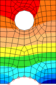
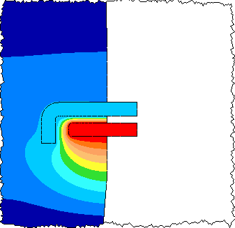
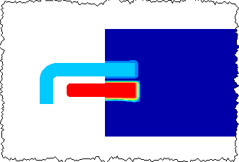
Some types of one-way coupling permit the meshes to be different in the two models. This allows the mesh to be optimized in both models. (Of course, the meshes can be identical also.) See Figure 1 for an example. Refer to the respective page for each loading type to see whether different meshes are supported or not.
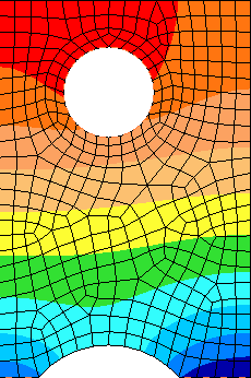
(a) Temperature results from a thermal analysis
(b) Loaded into a stress analysis with a coarser mesh.
(c) Loaded into a stress analysis with a finer mesh.
Figure 1: Mapping Temperature Results to a Different Stress Mesh
Requirements for Different Meshes
When the type of load supports different meshes in the two models, the model with the results must be a complete model. The results will be transferred between different meshes by mapping the nodes in each part of the result's model to the same part number in the target model. The mapping is as follows:
- For volume elements (2-D, brick, and tetrahedral), a different mesh can be used for these parts. The results are transferred from the results model to the target model as follows:
- Interpolation using shape functions will be used if the node in the target model are inside the volume of the results model.
- Projection will be used if the node on the target model is outside the volume of the results model but within tolerance of the mesh. See Figure 2.
- Any node in the target model that cannot be interpolated or projected will received the default load.
- For line elements (truss, beam, etc.) and area elements (membrane, plate, etc), the coordinates of the nodes in the parts must match between the two models. Thus, the same mesh must be used for these element types.
- The results and coordinates are converted from the units in the results model to the units in the target model if needed.
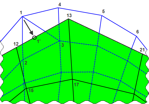
A highly magnified drawing (and exaggerated for clarity) of two meshes of the same part in two different models. The results are being transferred from the model shown in green and shaded to the mesh of the target model (shown in blue, un-shaded, and behind the mesh of the results model). Node 1 is outside the volume of the results mesh, so it is projected onto the surface of the results (point 1'). Shape functions are used to interpolate the result from element 12-13-17-15 to the nodes 1', 2, and 3. The result at 1' is assigned to node 1.
Figure 2: Example Node Mapping
Since the mapping is performed on a part-by-part basis, different parts can be activated or deactivated in each model. For example, imagine using the voltages from an electrostatic analysis in a stress analysis to calculate the piezoelectric effect. The electrostatic model may include the air in the analysis in order to have the proper electrostatic field. But the air is not relevant to the stress analysis, so it can be deactivated. Likewise, if there were a part needed for the stress analysis which has no influence on the electrostatic analysis, it can be deactivated in the electrostatic analysis. See Figure 2.
If only the results file exists, see the section "Requirements for Same Meshes" below.
(a) complete model with parts 2 through 5. Part 3 is an insulator, and part 4 is air.
(b) The voltage result from an electrostatic analysis. Part 3 is not included in the analysis.
(c) The voltage load in a stress analysis. Part 3 is included; part 4 is not included.
Figure 3: Different Part Numbers in Electrostatic and Stress Model
Requirements for Same Meshes
When the type of load requires the mesh in the two models to be identical, or if the complete model does not exist for the results, the results will be transferred by one of two methods (depending on the capability of the load type):
- transfer by node number. The result at node 1 will be transferred to node 1 in the target model, result node 2 will be transferred to target node 2, etc. Therefore, the models must be identical in node numbering.
- transfer by coordinates. The nodal coordinate in the results model must match one and only one nodal coordinate in the target model. Therefore, this method should not be used when more than one node exists at the same coordinate in space. This occurs most often when the contact type is something other than bonded and the parts are "in contact". For example, surface contact creates two nodes (one on each part) at the same coordinate. If transferring the temperatures from a thermal model to a stress model, you cannot control which temperature result from the matched nodes are transferred to which node.
If the input model does not exist and only the results file exist, then the transfer has to be done by the node number method.
Any extra nodes in the target model will receive the default load if one is defined.