The following message (and similar messages about zero stiffness and abrupt changes in stiffness) may occur in a model during the analysis:
Error: your model may not be tied down enough or you may have a change in stiffness in your model which is too abrupt. Check DOF 1365
1. Causes of the Error
This error indicates one of the following problems in your model:
- There is an abrupt change in the element stiffness from one section to another. This could be caused by either the element shape (which affects the stiffness) and/or material properties. The stiffness of gap elements may be too high relative to the model.
- One section of the model may not be connected properly to the rest of the model; consequently, a part of the model is not restrained. Check that the meshes match between different parts or different sections of the same part. The same mesh density was used along the common boundary between two regions. Using the Results environment with the Results Options
 View Show Numbers Node numbers switch activated, check for overlapping node numbers at the connection between different element groups. Or use the rectangle selection and draw a small box around one node. Does the Results Inquire Inquire Current Results list two nodes at the same coordinate? If so, the parts are not connected. If this is the case, change the snap tolerance and perform a global snap (Draw Modify Set Search Tolerance and Global Snap) or repair the problem manually.
 - The model does not have enough boundary conditions to be statically stable. Make sure the model is completely static in all six directions (translation in X, Y, and Z, rotation about X, Y, and Z).
- Different element types are not properly connected to produce a fixed connection, so a hinge has occurred. This often occurs with brick elements since they do not have a rotational degree of freedom and cannot transmit a moment to support other element types. See the page Meshing Overview: Creating Contact Pairs: Examples of Contact.)
2. Locating the Problem Node/Area
If the warning gives a node number, use the Results environment to locate the node. (Use Results Inquire Inquire Current Results Specify to select the node. Display a wireframe or unshaded view of the model to make it easier to see which node is selected: View Appearance Visual Style Features or View Appearance Visual Style Mesh.)
Otherwise, the number given in the warning message is an equation number or degree of freedom (DOF). To correlate the equation number to a node number, use the following:
- Run the analysis again if necessary using the Equation numbers data option in the Analysis Parameters screen under the Output tab. This will print a list of node numbers versus equation number. If you ran the analysis without the Equation numbers data runtime option and now need to run the model again to get the equation number table, you can also activate the Stop After Stiffness Calculations check box on the Solution tab. Since you know the analysis will not run completely, using this runtime option will cause the solver to halt after creating the stiffness matrix and the equation number table. Thus, the Stop After Stiffness Calculations check box can save some time.
- View the summary file in the Report environment. Search for the Equation Number section (use Ctrl+F to access the Search dialog). The table will look like the follow:
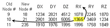
- Search the table for the number listed in the warning message (DOF 1365). This should be in one of the columns for the various degree of freedoms (DOF) Dx, Dy, Dz, and so on. (Depending on your element types, all degree of freedoms may not be listed.)
- After locating the equation number, move left to the first column. This shows which node is associated with the equation number. Move vertically in the same column as the equation number to find which degree of freedom it is associated with. In this example, equation #1365 corresponds to node number 10, degree of freedom Rx. This indicates that the processor wants node #10 constrained for rotation about the X-axis.
- In the Results environment, search for the location of node #10. Use the Results Inquire Inquire Current Results Specify command to enter node #10. The node will be selected in the model.
3. Solving the Problem
- If it appears that the problem is due to a lack of restraint, then you need to add additional boundary conditions to the model. Keep in mind that fixing the degree of freedom (DOF) reported may not be the best method of solving your problem. The processor only detects a problem; it is your responsibility to restrain the model at appropriate locations.
- If it appears the problem is due to a stiffness, then you may need to change the mesh or material properties. In some cases, it may be possible to add boundary conditions that do not affect the solution but do affect the stiffness matrix.
- If your model has gap or contact elements, check that all parts of the model are stable without relying on the gap elements. If any iteration has too few gap elements to restrain each part, the warning message will appear. To help the processor, it may be necessary to add very weak boundary elements to restrict the motion of the unconstrained parts. (Very weak boundary elements allow a static analysis to be performed during the first iteration. Then a change in gap status is determined, and the second iteration begins to consider the gap elements.) See the previous page Performing Analyses with Gap Elements for details.