Different types of issues can occur with the connection between different parts. One issue occurs when both parts are the same element type; the issue is whether the nodes are connected together as desired or not. Another issue occurs when the parts are different element types. In addition to the concern of whether the nodes are connected or not, there is an issue of what type of load is transmitted between the parts. This page will discuss some of these issues. See the previous page, Types of Contact, for the types of contact.
Note: Unless the description on this page specifically refers to smart bonding, the description is for contact that requires the meshes to be matched.
Bonded Contact Between Plates and Bricks:
The issue here is related to the degrees of freedom for each part are different. Bricks have only the three translational degrees of freedom (Tx, Ty, Tz) while plates (and shells) have all degrees of freedom except for rotation about the direction normal to the element. Therefore, the bricks cannot apply a moment to the plates that prevent the plates from rotating. Without special considerations, a connection between plates and bricks along a straight line of nodes will result in a hinge. This is depicted in Figure 1. In the case of linear stress, this may not be a statically stable configuration.
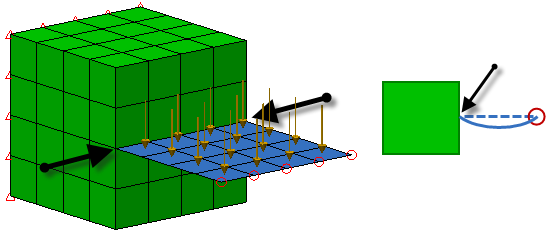
Figure 1 Hinged Combination of Bricks and Plates
The black arrows represent the hinge line. The schematic on the right shows a side view and how the plate deflects; note the rotation at the hinge line. If the free end of the plate was not supported, the plates is free to rotate around the hinge line which would result in a statically unstable situation.
To avoid this hinge effect, the bonded contact between the plate and brick needs to be distributed over an area; specifically, at least three nodes not in a straight line. See Figure 2.
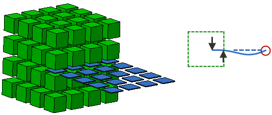
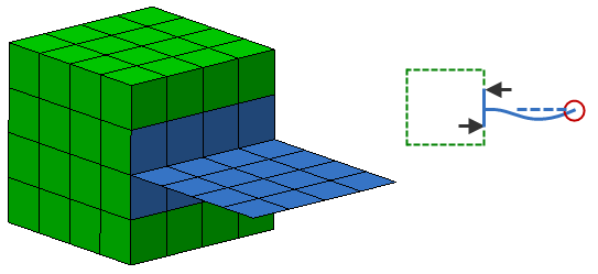
Figure 2 Statically Stable Combination of Bricks and Plates
In the top method, the plate is embedded one element deep into the bricks. (The elements are shrunk to show the space between them.) In the bottom method, a tee connection of plates is created on the surface of the bricks. In the schematics on the right which show the side view, visualize the arrows as the reactions provided by the bricks on the plate. (These are in fact the forces that are transmitted between the nodes of the bricks and plates.) Since the force couple can resist a moment load, the plate is now statically stable.
Bonded Contact Between Bricks and Beams:
The connected between beams and bricks has a similar problem to the plate-to-brick connection: the bricks cannot prevent the beams from rotating. The solution is likewise similar: make a web of beams (or spokes) to connect to the bricks. The beams must connect to the bricks at three or more points, not in a straight line, to form a statically stable solution. Figure 3 shows an example.
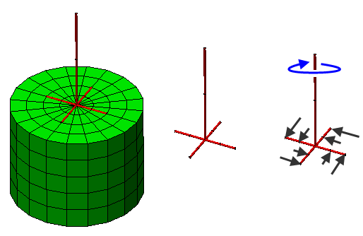
Figure 3 Statically Stable Combination of Bricks and Beams
The left side of the figure shows the beams and bricks together; the middle shows the beams only. Note how the vertical member is connected to four other beams that tie to the bricks at multiple points. If a torque were applied to the beams, such as in the schematic on the right side, then the black arrows represent the reactions provided by the bricks.
 Create Remote Load. If working with a CAD model, use the Draw Design Centroid Creator command. See the pages Setting Up and Performing the Analysis: Linear: Loads and Constraints: Remote Loads and Constraints and Meshing Overview: Creating and Modifying Geometry in the FEA Editor: Adding Geometry, respectively.
 Bonded Contact Between Plates and Beams:
There are two situations to consider when combining plates with beams.
- A plate cannot resist the moment about the axis normal to its face. Therefore, if you attach a beam normal to a plate, the plate element will not be able to keep it from rotating. To avoid this, it is recommended to add beams from the end of the normal beam to a few other nodes in the plate to form a statically stable model.
- If you model a beam lying on a plate, you must remember that you are drawing the midplane of the plate elements and the neutral axis of the beam elements. Therefore, if you draw a part of beams on the plate, you are really saying that the neutral axis of the beam lies along the midplane of the plate. This is most likely not accurate. There are two possible ways to model this correctly.
- You can draw the neutral axis of the beam and the midplane of the plate where they actually exist and connect them in several places with rigid beams to simulate the connection.
- You can draw the neutral axis of the beam along the midplane of the plate. Then select the beam elements using Selection Select Lines in the FEA Editor environment. Right-click in the display area and select the Add Beam Offset command. You will be able to specify the distance and direction between where the beam is drawn and where it is actually located.