We will create the upper weld as Part 3 and use the Mirror command to create the lower weld. The lines of the lower weld will then be modified to place them in Part 4.
- Click
 Draw
Draw  Draw Line. Type 3 in the Part: field.
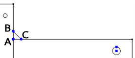
 - Click at the left end of the upper horizontal line on the horizontal part (Point A in the image below).
- Activate the Use Relative check box.
- Type 1 in the DZ: field and press Enter, creating line AB.
- Type 1 in the DY: field, type -1 in the DZ: field and press Enter, creating line BC.
- Click on point A, creating line CA.
- Press Esc once to end the chain of line segments but to leave the Line command active.
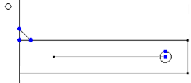
- Draw a construction line about which the weld will be mirrored.
- Click the construction vertex at the center of the large hole.
- Type -10 in the DY: field and press Enter to create the mirror line.
- Click Esc twice to exit the Line command. The mirror line will appear as shown below.
- Click and drag the mouse to draw a selection box enclosing only the upper weld objects.
- Select
 Draw Pattern Mirror.
 - Click Pick.
- Click the mirror line that was just created.
- Click OK to mirror the weld.
- Select
- The new copy of the weld will be selected. Change the part number for these lines while they are still selected.
- Click
 Draw Modify Attributes.
 - Type 4 in the Part: field.
- Click OK.
- Click
- Click on the horizontal line that was used to mirror the weld.
- Hold down Ctrl and click the construction vertex at the left end of the mirror line to select it also.
- Click
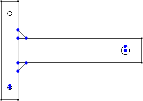
 Tools Clipboard Delete. Since this line does not belong to any of the part outlines, it must be removed before the 2D mesh can be generated. Note that you can also press the Delete key, rather than using the ribbon command.
 The model should display as shown in the following image.
 Tip: As an alternative, if you prefer to keep the mirror line, create it as Part 5 in step 3. Since Part 5 would not be a valid 2D part outline, simply deactivate this part to exclude it from the upcoming 2D mesh generation process and subsequent analysis.