Create a solid model of the circuit board assembly shown below using Inventor Fusion. All dimensions are in inches:
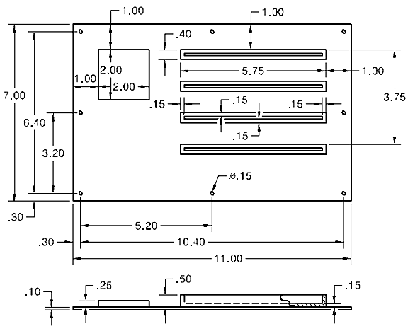
- The assembly consists of three parts—the board, the chip, and the edge connectors (all four connector bodies will be created as a single part using the Rectangular Pattern command).
- A single hole will be placed at a corner of the board and the remaining holes created by specifying a 3x3 rectangular pattern. One extraneous hole at the center of the board will be omitted from the 3x3 pattern, leaving only the eight holes shown in the above diagram.
- The Shell command will be used to hollow out the connector, leaving a wall thickness of 0.15 inch for the four sides and the bottom. The resulting slots will be 5.45 long x 0.1 wide x 0.35 deep.
- Use default material properties in Fusion for all three parts. The necessary thermal properties of the material will be defined within Autodesk Simulation during the subsequent tutorial.