Electrostatic 2D elements are 3- or 4-node triangular or quadrilateral elements formulated in the YZ plane. These elements act like conductors (resistive material) or dielectrics (insulators). The selected electrostatic analysis type (electrostatic field strength and voltage or electrostatic current and voltage) determines how they act. 2D elements are used to model parts such as insulators or to determine the deposition rate of material in electroplating solutions.
Types of 2D Elements
The two types of 2D elements available for an electrostatic analysis can be selected in the Element Definition dialog box, General tab, Geometry Type drop-down box:
- Planar Indicates that your model is planar in nature. Construct the model in the YZ plane. All loads are distributed uniformly across the thickness.
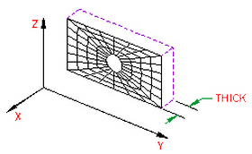
Figure 1: 2D Planar Elements
- Axisymmetric This type of geometry must have axial symmetry in both geometry and loading. Construct the model in the YZ plane, have the Z-axis as the axis of symmetry, and be in positive Y space. This geometry is based on the assumption that thickness-dependent quantities are expressed per radian. For example, all loads are distributed over one radian.
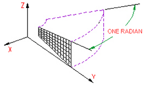
2D Axisymmetric Elements
Parameters of 2D Elements
When using 2D elements, if you are using the planar geometry type, define the thickness of the part in the Thickness field of the Element Definition dialog box. This input only affects the total current flow through an element face. It does not affect the voltage distribution nor the calculated current flux. If the geometry is axisymmetric, then this field is not available. The value 1 rad appears to remind you that an axisymmetric analysis considers a 1-radian slice.
Next, specify the material model for this part in the Material Model drop-down box. If the material properties in all directions are identical, select the Isotropic option. If the material properties vary along three orthogonal axes, select the Orthotropic option. If the material properties vary with the temperature, select either the Temperature-Dependent Isotropic or Temperature-Dependent Orthotropic option. If the Orthotropic or Temperature-Dependent Orthotropic option is selected, you can orient the material axes using the Principal Axes Transformation Angle field. The local n material axis will be measured this distance counterclockwise from the Y axis as shown in the following figure.
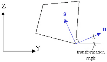
Figure 1: Principal Axes Transformation Angle
To Use 2D Elements
- Verify that a units system is defined.
- Verify that the model is using an electrostatic analysis type.
- Be sure that the elements that you are going to assign as 2D elements are drawn in the YZ plane. Tip: Useful commands for converting 3D models to 2D models are Draw
 Pattern Relocate & Scale, Draw Pattern Rotate or Copy, and Draw Modify Project to Plane. For example, you may accidentally create a mesh in the XY plane. You can rotate the mesh to the YZ plane using either the Relocate & Scale or Rotate command. Due to round-off, some nodes may have a small X coordinate value that prevents the element type from being set to 2D. In this case, use Project to Plane to snap the nodes exactly to the YZ plane.
 - Right-click the Element Type heading for the part that you want to be 2D elements.
- Select the 2D command.
- Right-click Element Definition, and then click Edit Element Definition.
- In the Material Model drop-down list, select the appropriate material model for the part.
- If the model is a constant thickness, in the Geometry Type drop-down box select Planar. If the model is symmetric about an axis of rotation, in the Geometry Type drop-down box, select Axisymmetric.
- If you are using planar elements, enter a value in Thickness.
- Click OK.