Now we will add a pin-joint between the holes of the two parts. The parts will rotate about the center of the holes.
- Click the Top face of the ViewCube and ensure that the view is in the rotational position shown below step 2. If necessary, click one of the rotation arrows above or to the right of the ViewCube to rotate the view to the upright position (the rotation arrows only appear while the cursor is on or near the ViewCube).
- Click
 View
View  Navigate Zoom Window. Draw a rectangle around the hole as shown in the following image to zoom into the fulcrum area. You can also access the
  Zoom Window command from the zoom fly-out menu on the Navigation Bar, if preferred.
 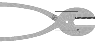 Note: Alternatively, you can
 scroll the mouse wheel with the cursor at the hole to zoom into the fulcrum area.
 - With the
 Selection Shape Circle and
  Selection Select Surfaces commands active, draw a circle enclosing the hole. The first click will be the center of the circular selection area and the second will indicate the radius. You may also click, drag, and release the button to define the selection area. You are selecting two surfaces, one cylindrical surface for each of two parts. Tip: Start selection circle at center of hole.
 - Click
 Mesh CAD Additions Joint and click OK to create the joint. The default type is "Pin Joint (lines to axis endpoints)." Lines from each vertex on the selected surfaces will converge at two endpoints along the centerline of the selected holes. Alternatively, a "Universal Joint (lines to axis midpoint)" can be created where appropriate (for example, to model a ball-joint connection). A universal joint is not appropriate for this model.
 - Click the heading for Part 3 in the browser to select the joint and make it more visible.
- Click the middle mouse button and drag to slightly rotate the model and inspect the joint. It appears as shown below:
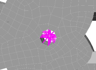
- Click the middle mouse button and drag to slightly rotate the model and inspect the joint. It appears as shown below:
- Click the Top face of the ViewCube. The model appears as shown in the following image.
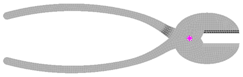
Note: Since trusses are used by default when creating joints, the parts will be free to rotate relative to each other, about the axis of the pin joint. Trusses only support axial loads and act as if each end were a frictionless ball-joint. If a torsionally rigid joint is needed, the element type can be changed to beams.
This tutorial is now complete. Save your model to use in the Vice Grips Static Stress Analysis tutorial.