Linear tetrahedral elements are either constant stress elements with four nodes or linear stress elements with 10 nodes. These elements are formulated in three-dimensional space with three degrees of freedom per node; these are the translational degrees of freedom in the X, Y and Z directions, respectively. The ten-node element is an isoparametric element and stresses are calculated at the nodes. The following element-based loadings may be applied:
- Uniform or hydrostatic pressure on the element faces.
- Thermal gradients defined by temperatures at the nodes.
- Uniform inertial load in three directions.
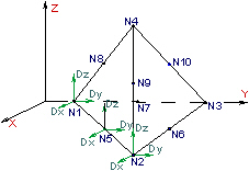
Figure 1: 10-Noded Tetrahedral Element
Determination Surface Number for Tetrahedrals
When applying loads to a surface number of a tetrahedral part, be aware that some models may not have all the lines on the face to be loaded on the same surface number. What happens in this situation? If the model originated from a CAD solid model, all faces coincident with the surface of the CAD model receives the load regardless of the surface number of the lines. In hand-built models and on CAD parts that are altered so that the part is no longer associated with the CAD part, the surface number that is common in any two of the three lines that define a face determines the surface number of that face.
Tetrahedral elements, by definition, cannot have rotational degrees of freedom (DOFs), even if you released these DOFs when applying the boundary conditions. You can apply translational DOFs as needed.
When to Use Tetrahedral Elements
- The stress results through the thickness of a part is preferred.
- The model has only forces applied, no moments. (Tetrahedrals have no rotational degrees of freedom). For advice on how to apply a moment to a tetrahedral element, see the page Meshing Overview: Creating Contact Pairs: Examples of Contact.
- The model has a hydrostatic pressure or pressure load applied.
Tetrahedral Element Parameters
If you want the tetrahedral elements in this part to have the midside nodes activated, select the Included option in the Midside Nodes drop-down menu. If this option is selected, the tetrahedral elements have additional nodes defined at the midpoints of each edge. (For meshes of CAD solid models, the midside nodes follow the original curvature of the CAD surface, depending on the option selected before creating the mesh. For hand-built models and CAD model meshes that are altered, the midside node is located at the midpoint between the corner nodes.) It changes a 4-node tetrahedral element into a 10-node tetrahedral element. An element with midside nodes results in more accurately calculated gradients. This is especially useful when trying to model bending behavior with few elements across the bending plane. Elements with midside nodes increase processing time. If the mesh is sufficiently small, then midside nodes may not provide any significant increase in accuracy.
 Model Setup Parameters dialog box. (The location under the Analysis Parameters varies from analysis type to analysis type.)
 Next, select the integration order that is used for the tetrahedral elements in this part in the Integration Order drop-down menu. For rectangular shaped elements, select the 2nd Order option. For moderately distorted elements, select the 3rd Order option. For extremely distorted elements, select the 4th Order option. The computation time for element stiffness formulation increases as the third power of the integration order. Consequently, the lowest integration order which produces acceptable results should be used to reduce processing time.
If you are performing a thermal stress analysis on this part, specify the temperature at which the elements in this part experiences no thermally induced stresses in the Stress Free Reference Temperature field. Element based loads associated with constraint of thermal growth are calculated using the average of the temperatures specified on the nodal point data lines. The reference temperature is used to calculate the temperature change. Thermal loading may be used to achieve other types of member loadings. For these cases, an equivalent temperature change (dT) is used.
To use Tetrahedral Elements
- Be sure that a unit system is defined.
- Be sure that the model is using a structural analysis type.
- Right-click the Element Type heading for the part that you want to be tetrahedral elements.
- Select the Tetrahedral command.
- Right-click the Element Definition heading.
- Select the Edit Element Definition command.
- To have midside nodes used in this part, select the Included option in the Midside Nodes drop-down box.
- If you are performing a thermal stress analysis, enter a temperature into the Stress Free Reference Temperature field. The difference between this value and the applied temperatures will be used to calculate the stress.