Autodesk Simulation CFD provides the ability to analyze rotating devices surrounded by a static (non-rotating) frame of reference. By physically rotating the device and the region immediately surrounding it, this capability offers greater flexibility for analyzing rotating machinery. Examples include pumps, fans, blowers, and turbines. Centrifugal, axial, and mixed configurations are supported, as are devices with multiple rotating components (such as the pump and turbine in an automotive torque converter).
This functionality provides the ability to analyze the flow within the blade passages of a rotating device., and also allows study of the interaction between rotating and non-rotating geometry. A classic example is the interaction between the rotor and the stator in an axial compressor or turbine. Another example is the influence of a volute cutwater (tongue) on the exit flow from a centrifugal pump impeller.
Geometric Considerations
The Autodesk Simulation CFD rotating machinery capability analyzes rotating devices using a locally rotating frame of reference. This region completely surrounds a rotating object, and is called the rotating region.
Areas in the model that are not rotating are analyzed in a static (absolute) frame of reference. These regions are called static regions. (Fluid in a static region can move, but the volume itself does not.)
The following are geometric considerations for setting up rotating analyses:
- Each rotating object must be completely immersed in a rotating region. Rotating regions rotate using their own relative rotating frame of reference.
- The mesh that is generated in a rotating region will physically rotate with the parts that are immersed.
- Immersed parts can be modeled as voids or as solid within the rotating region. Solid objects in a rotating region rotate at the same speed as the rotating region.
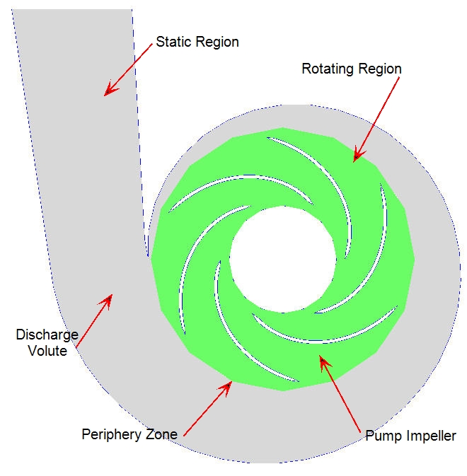
- The interface between a rotating and a static region is called the periphery zone. Within the periphery zone, the outer element faces of the rotating region slide along the neighboring element faces of the static region.
- The size and shape of a rotating region should correspond (loosely) to that of the rotating device. Rotating regions are usually fairly simple cylindrical shapes. This allows the element faces on both sides of the periphery zone to match.
- The rotating region should extend to roughly half-way between the outer blade tips and the closest point of the surrounding non-rotating wall.
- Do not apply any boundary conditions to the periphery zone. Care should be exercised when constructing fluid geometry so this is not necessary.
- Rotating regions must not overlap. Devices with interfering rotors such as gear pumps cannot be modeled with the rotating machinery capability because their rotating regions overlap. Instead, use angular motion.
- A rotating region cannot directly contact a non-rotating solid region, even if the solid is not inside of the rotating region. An example is a solid annulus surrounding the outside of rotating region. The result is that the solid annulus (which is supposed to be static) will rotate.
- Objects within a rotating region that have a uniform cross-section that satisfy the requirements for mesh extrusion can be extruded. The mesh inside of the rotating region, however, cannot be extruded.
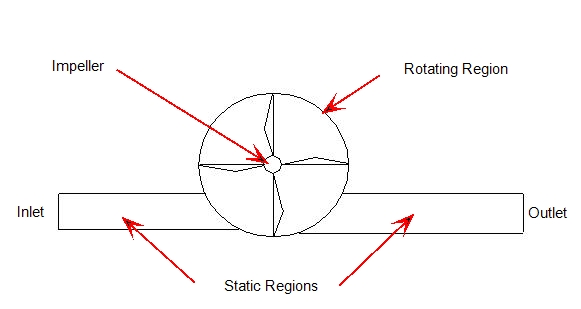
The following graphics illustrate these principals:
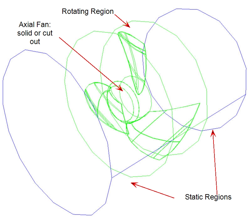
- If the blade tip clearance is extremely small (as is the case when there are tight seals), the surrounding static region can be eliminated. An example is shown:
- A rotating region must not be in direct contact with a solid region. The outer edge of the rotating region must either be a fluid or an exterior boundary.
Boundary Conditions
If the rotational speed of the rotor is known, then pressure boundary conditions can usually be specified. In many cases, the purpose of the analysis is to determine the flow rate for a given pressure. Apply a pressure rise across the device. This will impose the resistance faced (head).
We recommend starting such an analysis with equal pressures assigned to both the inlet and outlet. As the impeller starts rotating and moving flow, the pressure rise can be gradually imposed. This can be done either manually or with a time-varying boundary condition.
Another situation involving a known rotational speed is that the flow rate is known, and the pressure drop is the desired output quantity. For such a model, specify a pressure of 0 gage at the inlet and the flow rate at the outlet. This method will often solve faster than specifying a pressure on both the inlet and outlet.
If the rotational speed of the rotor is unknown (as in the case of the torque-driven or the free-spinning scenarios), then a specified velocity or flow rate is most often appropriate. Recall that a pressure MUST be assigned to at least one opening in the model unless the model is fully enclosed.
Heat transfer boundary conditions can be applied as appropriate to conduct a heat transfer analysis.
Using Frozen Rotor for solving rotating analyses
Frozen Rotor is an optional setting for rotating analyses that reduces simulation time and produces an approximate solution. Unlike a traditional rotating analysis, the rotating region does not rotate during the simulation. Rotation and associated momentum terms are imparted to the flow, however.
Frozen Rotor is useful for quickly simulating rotating devices without the complexity of numerically rotating the physical rotor. Note that Frozen Rotor does not predict interaction between rotating and non-rotating objects (such as rotor-stator or impeller-volute).
Frozen Rotor analyses are generally faster because Autodesk Simulation CFD does not update the rotating mesh position and the sliding rotor-stator interface with every time step. Because the rotor is static, you can use larger time steps which lead to a steady-state solution in less time.
Setup considerations
- Construct the analysis model geometry using the same geometric guidelines as for a traditional rotating region analysis.
- Use a larger time step than you would in a traditional rotating analysis. In fact, you can use the largest time step that maintains stability.
- As with traditional rotating analyses, we recommend ramping up the rotational speed to avoid impulsive starts.
- To enable Frozen Rotor, enable this flag in the Flag Manager: FrozenRotor
Rotating Region Output File
The Rotating Region Results file contains the time history of Rotating Region simulations. This file lists the hydraulic torque, rotating speed, and hydraulic force components for each rotating object.
Hydraulic Torque is the torque the blades must overcome to push through the fluid. This is different from torque imparted from a motor, which includes hydraulic torque plus bearing friction and shaft losses.
Hydraulic Forces are the forces imparted by the fluid on the impeller.
This data is also written to an external “.csv” file. The file name is the scenario name with the word torque appended to it. For example, the torque file from Scenario 1 is named: Scenario 1_torque.csv. This file is located in the scenario sub-folder of the design study directory structure.
Related Topics