If the vessel has multiple nozzles projecting from the main cylinder, then set the Type of model to generate drop-down box in the General tab to Multiple nozzles. This will deactivate the other tabs. The input is used only for a single nozzle vessel.
To generate a plate or shell element model, select the Plate/shell option in the Type of pipes generated drop-down box on the General tab. To generate a brick element model, select the Solid option. Note that the Preview Area does not show the thicknesses; it continues to show the plate/shell mesh.
The input for a multiple nozzle vessel is entered by pressing the Multiple nozzles button. This will display the Cylinder with Multiple Nozzles input dialog.
 Dialog Position menu to control where this input screen (and the other dialogs) first appear on the screen.
 Main Cylinder
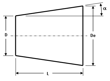
On the Geometry tab, specify the length, diameter (at -X end of cylinder) and taper angle of the cylinder. The centerline of the cylinder is on the X axis, and the end on the -X side is at the origin. The taper angle is defined as tan(angle a)=[0.5*(End Diameter - Diameter of cylinder)/(Length of cylinder)]. A positive taper angle means that the diameter is larger at the +X end of the cylinder than at the end specified (Diameter of cylinder (D1)).
|
|
|
Key: D = diameter of cylinder (user input) De = end diameter (calculated) L = length of cylinder (user input) α = taper angle (user input). Tan(α) = (De - D)/2/L |
| Figure 1: Tapered Cylinder |
Nozzles on Main Cylinders
Since the main cylinder can contain multiple nozzles, the following buttons on the Cylinder with Multiple Nozzles input dialog are used to manipulate the various nozzles:
- To create a nozzle on the cylinder, press the Add new nozzle button in the Geometry tab. Once you are done defining the nozzle, press the Add new nozzle button again to create the next nozzle. Repeat this until all nozzles have been added.
- To modify the properties of an existing nozzle, select the nozzle number in the drop-down box in the Nozzles on Cylinder section and press the Modify nozzle button.
- To remove a nozzle, select the nozzle number in the drop-down box in the Nozzles on Cylinder section and press the Remove nozzle button.
- If two nozzles are identical but are located at different positions, you can define the nozzle properties for one nozzle, select the nozzle number in the drop-down box in the Nozzles on Cylinder section and press the Duplicate nozzle button. A new nozzle will be created. You can then modify the position of the new nozzle.
When editing a particular nozzle (either when adding a new nozzle or modifying an existing nozzle), the Particular Nozzle dialog specifies all of the parameters for the position, size, heads on the nozzle, and so forth. The input is mostly self explanatory with the following clarifications:
- Use the Include nozzle on cylinder check box to activate or deactivate the nozzle. Deactivating the nozzle will hide it but retain the input.
- The Geometry tab gives the dimensions of the nozzle. Also,
- Taper angle of nozzle: Since the input diameter for the nozzle is at the end away from the intersection with the cylinder, a positive taper angle means that the nozzle is larger at the cylinder intersection than the opposite end. Using the nomenclature in Figure 1, Tan(α) = (De - D)/2/L where D is the user-entered diameter or dimension and De is the diameter or dimension of the nozzle at the cylinder.
- Orifice with no nozzle will create a hole in the side of the vessel using the nozzle type and dimensions.
- The Position tab is used to locate the nozzle on the cylinder.
- X value is measured from the -X end of the cylinder.
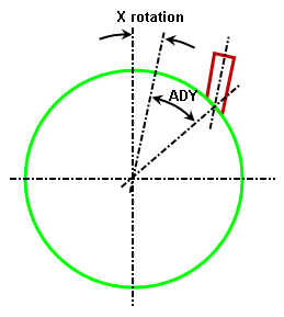
- X rotation follows the left-hand rule to rotate the nozzle about the X axis to the point of intersection. That is, a negative angle rotates the nozzle about the +X axis. The Offset method then moves the nozzle off of the X rotation axis. See Figure 2.
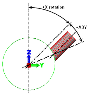
- The Offset method drop-down box is used to indicate how to specify the offset of the nozzle out of the plane of the X rotation. (If the X rotation were 0, the offset would be in the Y direction.) If the Distance option is selected, specify the distance perpendicular to the X rotation plane in the Nozzle's offset distance (DY) field. If the Angle option is selected in the Offset method drop-down box, specify the angle at which the nozzle intersects the cylinder in the Nozzle's offset angle (ADY) field. See Figure 2. This value follows the left-hand rule, so a negative angle rotates the nozzle about the +X axis.
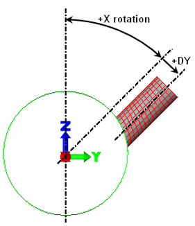
Offset of nozzle by distance
Offset of nozzle by angle
Note that the nozzle centerline is parallel to the centerline defined by the X rotation angle. When the offset is 0, the nozzle is perpendicular to the vessel. When the offset is nonzero, the nozzle is no longer perpendicular to the vessel. By using a combination of X rotation and offset, a nozzle can be created with any desired orientation.
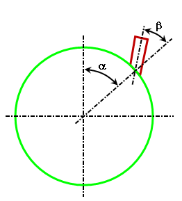
Example Vessel with known position of nozzle at angles α and β.
Input into PVDesigner.
X rotation = α-β. ADY = β.
- The nozzle can be rotated about the Y axis so that it is not parallel to the YZ plane. Specify the angle in the Angular rotation of nozzle (AR) field. Note that this value follows the left-hand rule, so a negative angle rotates the nozzle about the +Y axis. See Figure 3.
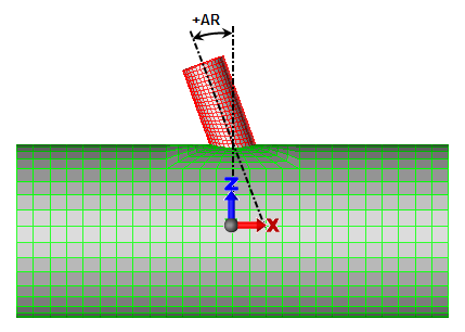
Figure 3: Rotation of Nozzle About Y Axis.
A positive angle is shown. Note that the angle follows the left-hand rule.
Nozzles on Heads
After a head is added to the main cylinder or to a nozzle on the main cylinder (see below), a nozzle can be added to the head! On the dialog where the head is defined, activate the check box Include nozzles on head, and then click the Nozzles on head button. Refer to the page Nozzles on Heads for details.
Flanges and Repads
Flanges can be added to either end of the cylinder from the main Cylinder With Multiple Nozzles dialog. From there, use the Extras tab to specify the parameters for the flanges.
Flanged can be added to the end of a nozzle. Modify the nozzle of interest to display the Particular Nozzle dialog, then go to the Extras tab. Enter the desired dimension.
Repads around the nozzle to main cylinder intersection are also added from the Extras tab for the appropriate nozzle; that is, modify the nozzle of interest to display the Particular Nozzle dialog, then go to the Extras tab.
Add Heads to the Cylinder and Nozzles
Heads can be added to the cylinder from the main Cylinder With Multiple Nozzles dialog. Go to the Extras tab and click the Heads button. This will access the Heads on Cylinder dialog.
Heads can be added to the end of any nozzle attached to the main cylinder. Modify the nozzle of interest to display the Particular Nozzle dialog, then go to the Heads tab.
Whether adding a head to the cylinder or a nozzle, the input is similar. See the page Heads Dialog for details.
Set Part Numbers:
Each piece of the vessel (cylinder, nozzle, repads, and so on) can be created on a different part number. Recall that the part number controls parameters such as the material properties, and the thickness of the part and which side is top and bottom for pressure loading (for plate/shell models).
Part numbers for the cylinder are specified from the main Cylinder With Multiple Nozzles dialog. From there, use the Parts tab.
Part numbers for each nozzle are specified by modifying the nozzle of interest to display the Particular Nozzle dialog, then go to the Parts tab.
Set Mesh Density
You can control the mesh spacing used for each part of the pressure vessel. For the main cylinder, flanges and heads on the cylinder, go to the Mesh tab on the main Cylinder With Multiple Nozzles dialog.
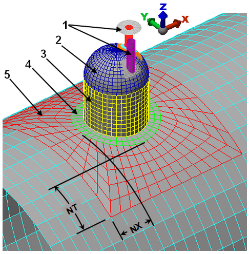
For the mesh around the nozzles, transition region, flange, repad, and heads on the nozzle, modify the nozzle of interest to display the Particular Nozzle dialog, then go to the Mesh tab. In addition to specifying the number of divisions, the size of the transition region around the nozzle to cylinder intersection is controlled by the Ratio of transition to cylinder diameter input. The dimension of the transition region, measured from the nozzle (or edge of the repad if included), is equal to or greater than the ratio input value times the cylinder diameter. The actual dimension of the transition region is adjusted to fit the mesh on the cylinder. See Figure 4.
|
|
|
Key: 1 = nozzles on head 2 = head on nozzle 3 = nozzle on cylinder 4 = optional repad on the cylinder 5 = transition region on the cylinder NX = distance between nozzle (or repad if it exists) and end of transition region in the axial direction. NX>=Ratio*cylinder diameter. NT = distance between nozzle (or repad if it exists) and end of transition region in the sweep direction. NT>=Ratio*cylinder diameter. |
| Figure 4: Transition Mesh Between Nozzle and Cylinder |
To create a nonstructured mesh, you must own the ability to mesh CAD models, then:
- Use the PVDesigner File Export command and set the Save as type to Solid (*.igs).
- Exit PVDesigner to return to Autodesk Simulation.
- Use
 Open and set the Files of type to IGES.
 - Once the IGES file is opened, set the mesh type as Plate/shell and mesh the model. Note: The File Export command does not create a solid IGES file of a solid multiple nozzle type, only the plate/shell multiple nozzle type.
Define Thickness
If you are creating a brick model, the thickness of each part can be specified on the appropriate Thickness dialog. For example, the dialog for entering the main cylinder dimensions includes a Thickness tab, the dialog for entering the main cylinder nozzle dimensions includes a Thickness tab, and the dialog for entering the nozzle on a head includes a Thickness tab. (For plate/shell meshes, the thickness of each region is specified in the FEA Editor under the Element Definition.)
EditPressure Vessel), then modify the nozzle (Multiple nozzles Modify Nozzle). If the problem occurs with the nozzle to main cylinder intersection, use the Mesh tab to increase the Ratio of transition to cylinder diameter or Mesh division along width of transition region. If the problem occurs with the nozzle to head intersection, use the Heads tab, then Nozzles on head button, then Mesh tab to increase the Transition region ratio or Mesh division along width of transition region.