We will now apply the surface constraints to the symmetry planes and a nodal constraint to the bottom of the vessel.
- Click
 View
View  Navigate Orientation Front View.
 - With the
 Selection Shape Point or Rectangle and
  Selection Select Surfaces commands active, click and drag to draw a rectangle enclosing the top edge of the model, as shown below.
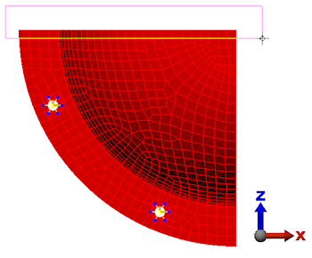
- Click
 Setup Constraints General Constraint.
 - Click the Z Symmetry button.
- Click OK.
- Draw a selection rectangle enclosing the right edge of the model, as shown below.
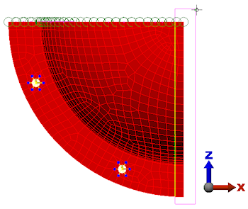
- Click Setup Constraints General Constraint.
- Click the X Symmetry button.
- Click OK.
- Click the Home
 icon that appears above the ViewCube when the cursor is in that area. An isometric view of the model is displayed.
 - Select
 View Navigate Zoom Window. Draw a box around the bottom corner of the pressure vessel to zoom into this corner, as shown in the following image.
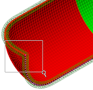
- Press Esc to exit the zoom area command.
- With the
 Selection Select Vertices command active, click the node at the bottom corner of the model, as shown highlighted below.
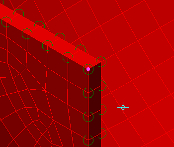
- Click Setup Constraints General Constraint.
- Click the Fixed button.
- Click OK.