Create the board as a thin solid box and add the mounting holes.
- Right-click the Board:1 heading in the browser and select Activate Component.
- Click
 Home
Home  Solid Box.
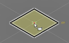
 - The drawing plane defaults to XY and the view is isometric. Click the red dot at the coordinate origin to begin the solid box.
- Click the light bulb glyph (
 ) next to the Origin heading in the browser to make the global axes visible. You can see that the X direction, as currently viewed, is down and towards the right, while the Y direction is up and towards the right.
 - Drag the mouse to the right to start a rectangle in the +X, +Y quadrant.
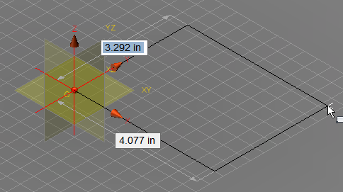
- Typically, the Y dimension will be initially highlighted. However, if the X dimension is highlighted first, reverse the order of entry of the two dimensions listed below. Type the appropriate first dimension, press Enter to lock it in and to advance to the second dimension field, type the appropriate second dimension, and press Enter again. Note that a padlock glyph appears next to a dimension when it is locked-in.
- Y dimension = 7
- X dimension = 11 Tip: You do not need to click in the dimension text fields. Just type a dimension and the currently highlighted field will be overwritten with the keyboard input. Be careful not to move the mouse before pressing enter and locking in the correct dimension. A significant mouse movement will unlock and change the dimensions.
- Press Enter one more time to accept the rectangle and then drag the mouse vertically to begin extruding the box in the +Z direction.
- The extrusion distance is now highlighted, but this dimension may be off-screen. If it is, in the Navigation Bar, choose
 Zoom All from the zoom fly-out menu.
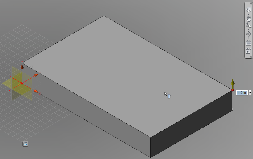
- Type 0.1 and press Enter to lock-in the Z dimension.
- Press Enter once more to create the box.
Show Me Step 2
Click the Play button to see a video of Step 2.
- The drawing plane defaults to XY and the view is isometric. Click the red dot at the coordinate origin to begin the solid box.
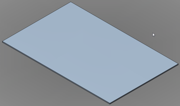
- In the Navigation Bar, click Zoom All once more to enclose the model.
- Click the light bulb glyph () next to the Origin heading in the browser one more time to hide the global planes and axes. The board should appear as shown below.
- Click
 Home Solid Hole.
 - Click on the top surface of the board one to two inches away from the bottom-left corner. The location is not important since the exact edge distances of the hole will be specified in the next steps.
- Click the short edge of the top surface at the left end of the model. A dimension field will appear allowing you to specify the distance from this edge to the center of the hole.
- Type 0.3 and press Enter.
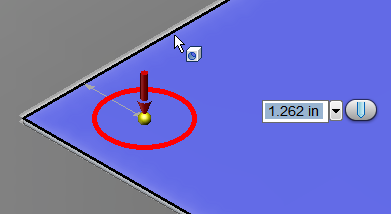
- Click the long edge of the top surface at the bottom end of the model. A dimension field will appear allowing you to specify the distance from this edge to the center of the hole.
- Type 0.3 and press Enter.
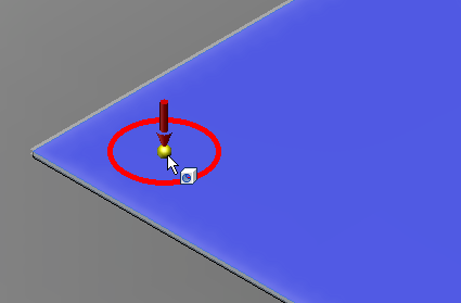
- Click the red circle. The circle will turn yellow and a diameter field will appear.

- Type 0.15 and press Enter.
- Click the red arrow and drag downward to indicate the direction and depth of the hole. The depth is not important as long as it equals of exceeds the board thickness (0.1 inch).
- Press Enter to complete the hole.
Show Me Step 5
Click the Play button to see a video of Step 5.
- Press Enter to complete the hole.
- Click on the top surface of the board one to two inches away from the bottom-left corner. The location is not important since the exact edge distances of the hole will be specified in the next steps.
- Click
 Home Solid Rectangular Pattern.
 - Expand the Board:1 branch of the browser and select the Hole2 subheading.
- Click
 Pattern Selections Direction.
 - Click one of the long edges of the board. Yellow and red direction arrows will appear at the hole.
- Click and drag the yellow (X-direction) arrow towards the opposite end of the circuit board. Note that the pattern defaults to three holes in this direction, which is what we need.
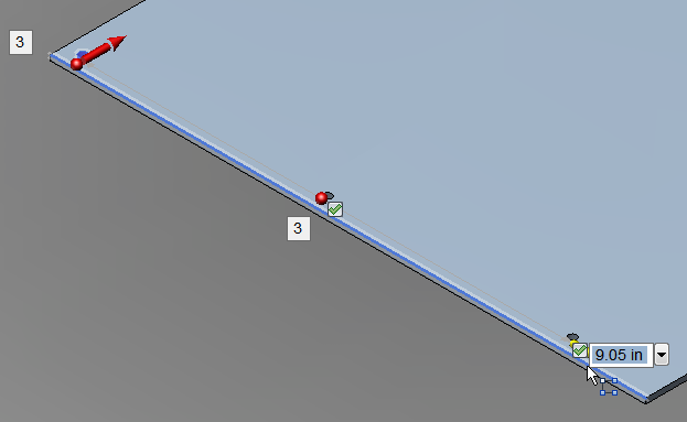
- Type 10.4 and press Enter. The field indicating the number of holes in the pattern is now highlighted. Important: Do NOT press Enter to confirm the number 3 because that would complete the command, leaving a pattern of holes in only the one direction. Press Enter again only if you change the number of holes in the pattern, which accepts the changed value but allows you to continue to define the pattern in a second direction.
- Click and drag the red (Y-direction) arrow towards the top edge of the board. Note that the pattern once again defaults to three holes in the Y-direction, as we want.
- Type 6.4 and press Enter.
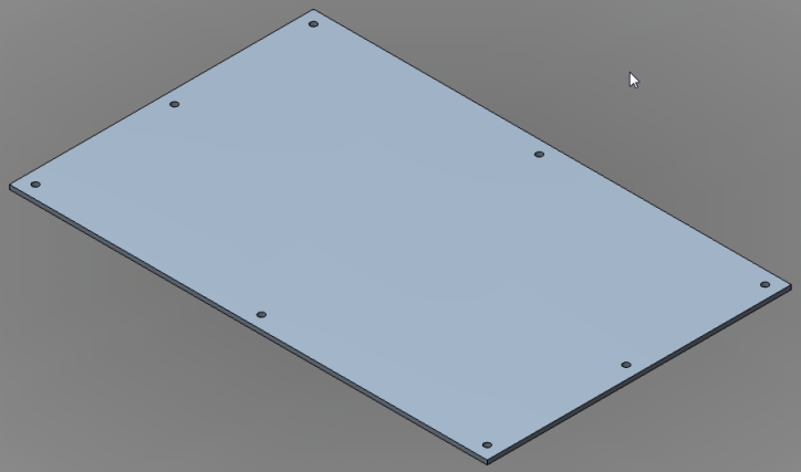
- There is a green checkmark next to each of the nine holes in the pattern. We need to exclude the hole at the very center of the board. Click the checkmark next to this hole. It will change to a red X and the hole will be eliminated.
- Press Enter to complete the command and create the pattern of eight holes. The board should look like the image below.
Show Me Step 6
Click the Play button to see a video of Step 6.
- Expand the Rectangular Pattern subheading under the Board:1 heading. Notice that the Occurrence5 subheading is missing from the list under the Rectangular Pattern heading (the list skips from Occurrence4 to Occurrence6). We excluded the fifth hole of a nine-hole pattern. Tip: It is also possible to delete individual items from a pattern after the pattern has been created by right-clicking on an OccurrenceX subheading and selecting the Delete command.
- This completes creation of the board. In the QAT, click
 Save.
Save.