Add the chip to top of the circuit board and then position it at the specified distances from the board edges.
- Right-click the Chip:1 heading in the browser and select Activate Component.
- Click
 Home
Home  Solid Box.
 - Click on the top surface of the board an inch or two from the top left corner. The position is not critical at this step. We will constrain the location later.
- Drag the mouse towards the opposite corner of the board to start a rectangle. One of the two dimensions will be highlighted.
- Type 2 and press Enter to lock in the dimension. The other dimension field will then be highlighted.
- Type 2 and press Enter to lock in the second dimension.
- Press Enter once more to accept the rectangle.
- Drag the mouse upward to extrude the chip in the +Z direction.
- Type 0.25 and press Enter to lock-in the height.
- Press Enter once more to complete the Box command.
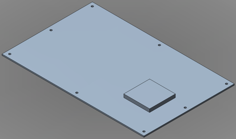
- Click on the topmost corner of the ViewCube, as currently oriented for the isometric Home view. This is the corner where the Top, Left, and Back faces meet.
- If necessary to enclose the view, click the Zoom All command in the Navigation Bar. The view of the assembly should now be as shown below.
- Click
 Home Constrain & Dimension Assemble.
 - Using the image below for guidance, select edge A.
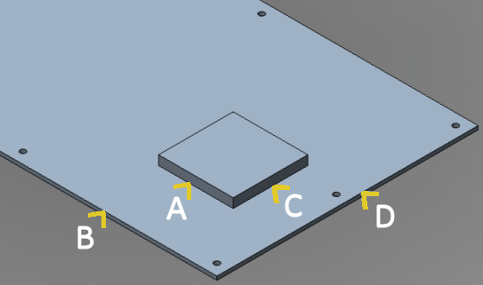
- Select edge B. The chip will move to the edge of the board and an offset dimension field will appear with the text highlighted.
- Type 1 and press Enter to lock-in the dimension. The chip will now be 1 inch away from edge B.
- Click edge C.
- Click edge D. The chip will move to the edge of the board and an offset dimension field will appear with the text highlighted.
- Type 1 and press Enter to lock-in the dimension. The chip will now be 1 inch away from edge D.
- Press Enter once more to complete the Assemble command.
- Using the image below for guidance, select edge A.
- In the QAT, click
 Save.
Save.