Create an edge connector using the Box and Shell commands. Position the connector correctly and then use the Rectangular Pattern command to create three additional connectors.
- Right-click the Edge Connectors:1 heading in the browser and select Activate Component.
- Click the upper left corner of the ViewCube as currently oriented. This is the corner where the Top, Back, and Right faces meet.
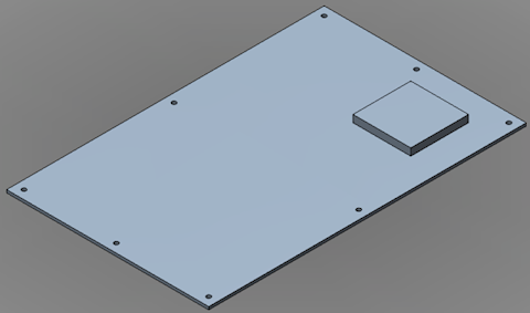
- If necessary to enclose the view, click the Zoom All command in the Navigation Bar. The model will be positioned as shown below.
- Click
 Home
Home  Solid Box.
 - Click on the top surface of the board an inch or two from the corner nearest the bottom of the screen. The position is not critical at this step. We will constrain the location later.
- Drag the mouse towards the opposite corner of the board to start a rectangle. One of the two dimensions will be highlighted. The rectangle needs to be 5.75 inches long x 0.4 inches wide. Enter the dimensions in the appropriate order, depending upon which field is highlighted first.
- Type 5.75 for the length, which is parallel to the long edge of the board, and press Enter to lock in the dimension.
- Type 0.4 for the width, which is parallel to the short edge of the board, and press Enter to lock in the second dimension.
- Press Enter once more to accept the rectangle.
- Drag the mouse upward to extrude the edge connector in the +Z direction.
- Type 0.5 and press Enter to lock-in the height.
- Press Enter once more to complete the Box command.
- Click
 Home Solid Shell.
 - Click the top face of the edge connector. A shell thickness field will appear with the dimension highlighted.
- Type 0.15 and press Enter to lock-in the shell thickness.
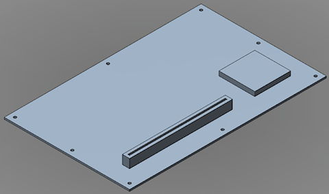
- Press Enter once more to complete the Shell command. The assembly should now appear as shown below.
- Click
 Home Constrain & Dimension Assemble.
 - Click the visible bottom, long edge of the edge connector.
- Click the near, long edge of the board.
- Type 1 in the offset field and press Enter.
- Click the visible bottom, short edge of the edge connector.
- Click the near, short edge of the board.
- Type 1 in the offset field and press Enter.
- Press Enter once more to complete the Assemble command.
- Click the visible bottom, long edge of the edge connector.
- Click
 Home Solid Rectangular Pattern.
 - Expand the Edge Connectors:1 branch of the browser and select the Solid subheading.
- Click
 Pattern Selections Direction.
 - Click one of the short edges of the edge connector to indicate the pattern direction. Yellow and red direction arrows will appear.
- Click and drag the Y-direction arrow towards the opposite end of the circuit board. Note that the pattern defaults to three items in this direction, which we will change to four after specifying the pattern distance.
- Type 3.75 and press Enter to lock-in the dimension. The field indicating the number of items in the pattern for this direction will now be highlighted.
- Type 4 and press Enter. The field indicating the number of items in the pattern for the other direction will now be highlighted.
- Type 1 and press Enter, since we only want a 1x4 pattern of edge connectors.
- Press Enter once more to complete the Rectangular Pattern command.
- Click the Home icon (
 ) next to the ViewCube to return to the default isometric view. Note that this icon is not visible until the cursor is over the ViewCube area.
 - This completes the construction of the Circuit Board model. In the QAT, click
 Save. The model appears as shown below.
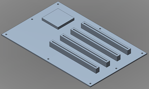
Normally, you could transfer the model immediately into Autodesk Simulation by clicking  Home Simulation Simulation Mechanical. However, for the analysis that will follow, we must change the CAD import options for Autodesk Simulation. We will do that during the Mesh Circuit Board CAD Model tutorial. If you are going to proceed directly to this tutorial, leave Fusion running with the Circuit Board model loaded. Just minimize the Fusion window and proceed to the
Mesh Circuit Board CAD Model
tutorial.
Home Simulation Simulation Mechanical. However, for the analysis that will follow, we must change the CAD import options for Autodesk Simulation. We will do that during the Mesh Circuit Board CAD Model tutorial. If you are going to proceed directly to this tutorial, leave Fusion running with the Circuit Board model loaded. Just minimize the Fusion window and proceed to the
Mesh Circuit Board CAD Model
tutorial.
Otherwise, you can:
- Return to the main page of the Meshing and Modeling Tutorials.
- Go to the main page of the Analyzing and Evaluating Results Tutorials.