Using this option, you can define spread footings in both 3D and 2D views of a structure model. Spread footings (which are prefabricated elements) are inserted in horizontal plans of a given story (in the top view).
To begin defining the spread footing, open the Spread Footing Definition dialog from:
- Menu: Formwork Drawings > Define > Spread footing
- Ribbon: ASD - Model > Elements > Spread footing
- Toolbar: Define > Spread footing

- Command line: RBCX_DEF_FOOT.
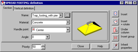
Use the tabs on the Spread Footing dialog to define parameters:
For Priority enter a value that defines the priority of interpenetration (cutting to fit) of structure elements that overlap with each other.
Use the icons on the right to select a mode of parameter definition:
- Click
 (Insert) to create a spread footing based on parameters you define in the dialog
 - Click
 (Insert + rotate) to create a spread footing and define graphically its rotation with respect to the insertion point (the angle is defined by selecting a point in the direction of which the spread footing will be facing)
 - Click
 (Under column) to specify a column in the drawing.
 - Click
 (Insert group) and specify 2 points of a rectangular workframe region - a spread footing with the specified parameters will be defined at all workframe points positioned inside that region
 - Click
 (Inherit properties) located in the bottom right corner to adopt parameters from a previously defined spread footing.
See also: