The kitchen cabinets you will create in this tutorial are based on the dimensions provided in the next diagram. In North America, the standard for kitchen cabinet height and width is inches, in increments of three. This diagram therefore uses feet and inches rather than metric units of measure.
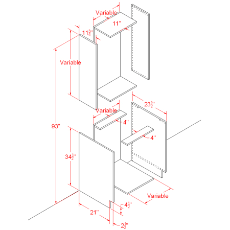
Line diagram showing kitchen cabinet dimensions
The diagram includes variable dimensions to account for varying cabinet width and height.
Possible cabinet width starts at 9 inches and increases incrementally by 3 inches to a total of 36 inches per cabinet.
The height of wall cabinets can be as little as 12 inches, increasing by 3 inches up to 30 inches, with one more dimension possible at 39 inches.
The standard height of a base cabinet is 34.5 inches, plus 1.5 inches for the countertop.
For most structures, 93 inches is the maximum height from the top of a variable-sized wall cabinet to the floor.
With the diagram as a guide, you will use modeling tools from the ribbon to create a group of cabinets of various sizes.
To start, you will build a base cabinet 18 inches wide.
Set up the lesson:
- On the Quick Access toolbar, click
 (Open File), navigate to the \scenes\modeling\kitchen_cabinets folder, and open
kitcab_start.max.
Note: If a dialog asks whether you want to use the scene’s Gamma And LUT settings, accept the scene Gamma settings, and click OK. If a dialog asks whether to use the scene’s units, accept the scene units, and click OK.
(Open File), navigate to the \scenes\modeling\kitchen_cabinets folder, and open
kitcab_start.max.
Note: If a dialog asks whether you want to use the scene’s Gamma And LUT settings, accept the scene Gamma settings, and click OK. If a dialog asks whether to use the scene’s units, accept the scene units, and click OK.The scene contains no geometry, but its units have been set up to use U.S. Standard feet and fractional inches measured in 1/32 of an inch. The scene also contains materials for the cabinets.
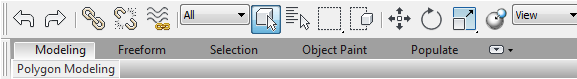
By default, a minimized version of the Graphite Modeling ribbon displays directly below the main toolbar.
 Note: This lesson provides descriptions for workstations using a default ribbon toolbar display. The ribbon on your workstation might display differently if you customized it in a previous 3ds Max session.
 - Click the
 expand/minimize icon a few times until the full ribbon displays.
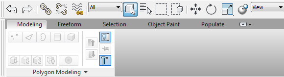
The Polygon Modeling tab displays with deactivated tools, since no polygon model exists in the scene.
Create the left cabinet board:
- Activate the Perspective viewport, then press
 +W to maximize it.
 - On the
 Create panel, activate
  (Geometry), then on the Object Type rollout, click to activate Box.
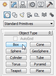
- In a viewport, drag out a box of any size.
- Go to the
 Modify panel, and on the Parameters rollout, set Length to 21.0, Width to 0.75, and Height to 34.5.
 As soon as you type in the values, they are converted to inches and fractions of 1/32 inch, based on the unit setup specified in the scene file.
Tip: As you go through these lessons, it might help to remember that 0.75” = 24/32”.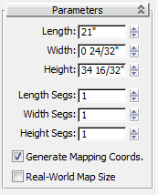
- On the main toolbar, activate
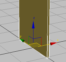
 (Select And Move), then on the status bar, right-click the X and Y transform spinners to set each of them to 0.0. (The Z value should already be 0.0: Make sure that it is.)
The center of the box is now at the center of the world coordinates.
- Go to the
 Hierarchy panel, and in the Adjust Pivot rollout
  Move/Rotate/Scale group, click to turn on Affect Object Only.
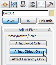
Now, if you move the object, its geometry moves but its pivot point remains unchanged at the center of the world.
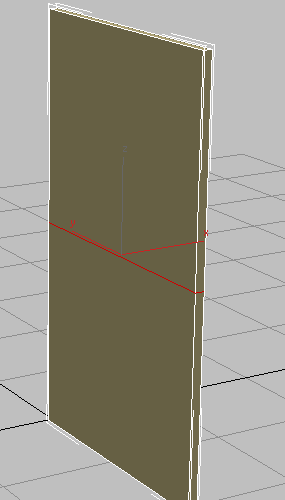
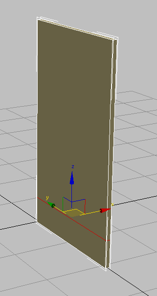
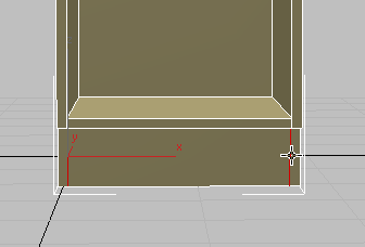
- In the Y transform box, type –10.5, which is equal to half the length of the box. Press
 .
. 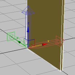
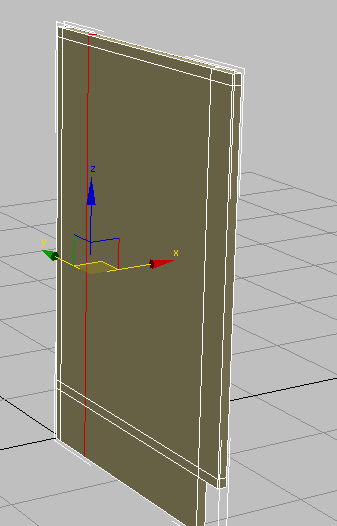
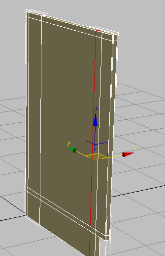
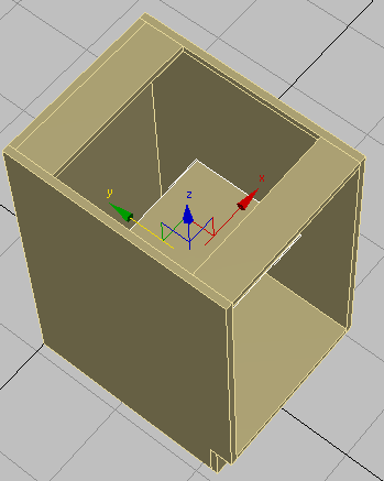
Box with pivot point repositioned to center of world coordinates (0,0,0)
The back face of the box and the pivot point are now both at the center of the world. The cabinet you are about to create from this object will now be much easier to manipulate.
- Click Affect Object Only again to turn it off.
Add polygon edges:
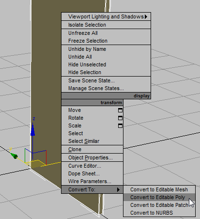
- Make sure the box is selected, right-click it, and from the Transform (lower-right) quadrant of the quad menu choose Convert To Convert To Editable Poly.
The ribbon updates to display a range of polygon-editing tools.
- On the ribbon Polygon Modeling panel, activate
 (Edge).
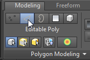
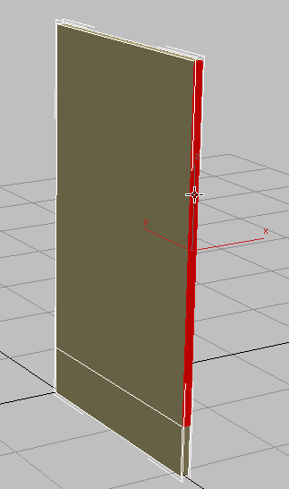
-
 Drag a selection region across the center of the box to select all its vertical edges.
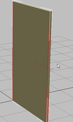
- On the ribbon Loops panel, click
 (Connect).
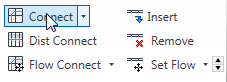
This connects all selected edges by drawing a loop around them through their midpoints.
Loop created from selected edges
- On the main toolbar, activate (Select And Move), and in the Z transform field, type 4.5, then press .
This moves the new connecting edges closer to the floor.
- On the ribbon Polygon Modeling panel, activate
 (Polygon).
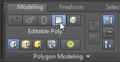
- Click to select the upper face on the front of the panel.
- On the ribbon Polygons panel,
 +click
  (Extrude).
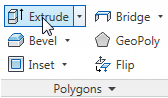
(When you
+click one of these tools, 3ds Max displays the caddy controls for that tool.) 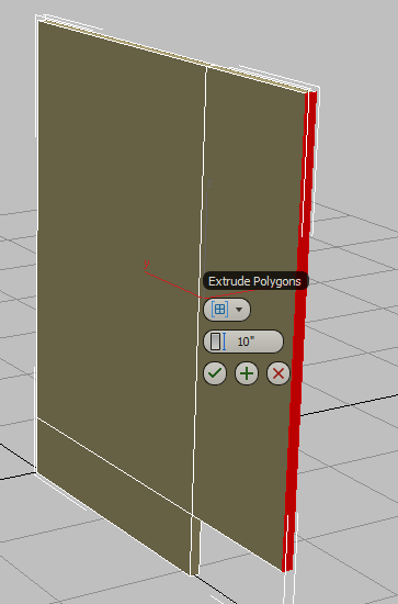
- On the second control of the Extrude caddy, Height, set the value to 2.5, then click
 (OK).
(OK). 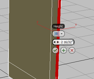
Now you need to add more detail to the side of the box so you can later connect this panel to the rest of the model.
Next, you’ll add edges to your object. These edges will create the polygon faces you will need for extrusions later in the modeling.
Add detail to the left board:
- On the ribbon Polygon Modeling panel, activate (Edge) once more.
- On the ribbon Edit panel, click
 (SwiftLoop).
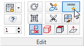
Now, as you position your cursor near an edge, a green virtual loop displays. This helps you visualize the placement of the loop.
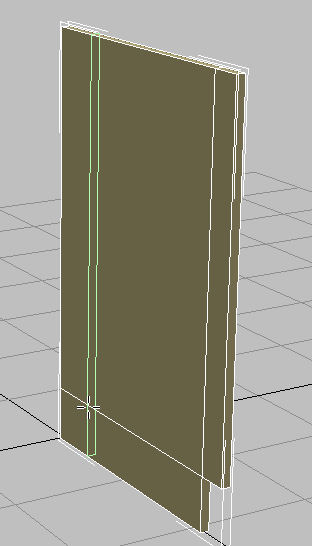
- In the viewport, click a horizontal polygon edge.
3ds Max creates a loop perpendicular to the edge you clicked. This method is a fast way to create and position a loop on a model.
Based on the diagram, you want the loop to be positioned 0.75 inches from the back edge of the box.
- On the main toolbar, activate (Select And Move), then in the Y transform field, type –0.75.
 Note: Activating Select And Move turns off SwiftLoop.
 - On the ribbon Edit panel, click (SwiftLoop) to activate it again.
- In the viewport, click a vertical edge anywhere in the upper part of the panel.
- On the main toolbar, activate (Select And Move), then in the Z transform field, type 5.25.
This value represents the height of the toe space created by the extrusion in step 7, plus the thickness of the cabinet floor board you will soon create.
- On the ribbon Edit panel, activate (SwiftLoop) again.
- In the viewport, click a vertical edge anywhere in the upper part of the panel.
- On the main toolbar, activate (Select And Move), then in the Z transform field, type 33.75.

This value represents the height of the base cabinet, less the 0.75-inch thickness of the four-inch support boards you will soon create.
- On the ribbon Edit panel, activate (SwiftLoop), then click a horizontal edge anywhere around the midpoint of the panel.
- On the main toolbar, activate (Select And Move), then in the Y transform field, type –4.75.
This represents the width of the support board, plus the thickness of the rear cabinet board.
- Place another vertical loop, then on the main toolbar, activate (Select And Move), and in the Y transform field, type –19.5.
This represents the width of the support board, less the length of the side cabinet board.
Now you have all the subdivisions required to build upon this cabinet component.
You continue by adding an edge toward the rear of the box to allow for the inclusion of a back panel to the cabinet that is 0.75 inches thick.
Create the opposite side of the cabinet:
- On the ribbon Polygon Modeling panel, click
 (Edge) to exit the Edge sub-object level.
 - From the Edit menu, choose Clone. In the Clone Options dialog Object group, choose Copy, and then click OK.
- Activate (Select And Move). On the X transform box, type 17.25.
The width of the cabinet you are building is 18 inches, measured from the outside left of the cabinet to the outside right. Therefore, the value of 17.25 represents the full 18 inches, less half the width of the left and half the width of the right cabinet boards (which combined, equal 0.75 inches).
- In the viewport, select the original cabinet board, on the left, and on the ribbon Geometry panel, click
 (Attach) to turn it on.
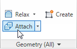
- In the viewport, click the right (cloned) cabinet board.
This combines both boards into a single object.
Create the counter supports:
- On the ribbon Polygon Modeling panel, activate (Polygon), then click an empty part of the viewport to make sure no polygons are selected.
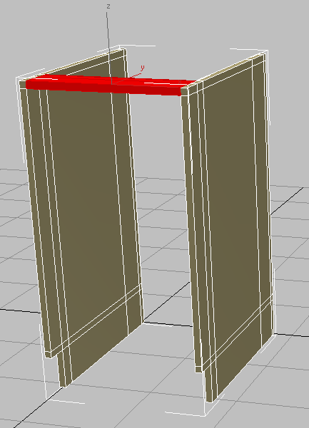
- Click and
 +click the two polygons at the upper-right corner of the panel on the right. This is where the front counter support will be attached.
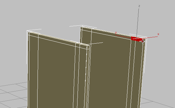
-
 Orbit so you can see the corresponding corner polygons on the inside of the left panel, then +click to select these as well.
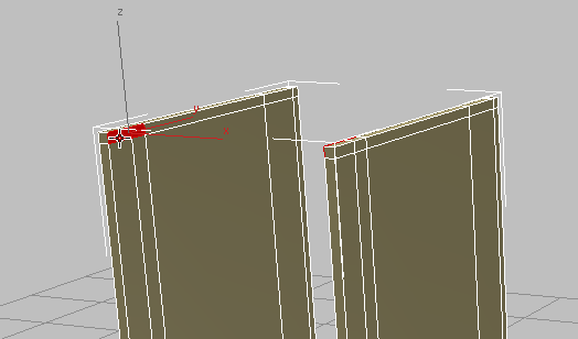
- On the ribbon Polygons panel, click
 (Bridge).
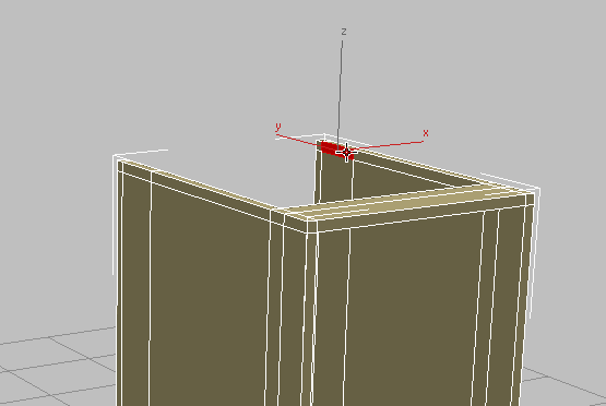
3ds Max connects the selected polygons to one another.
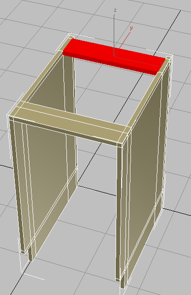
Front support created from selected polygons
- Press +Z to undo the view change.
- Click to select the single polygon where the other counter support will be attached. Don’t select the small face at the very rear of the cabinet.
- Orbit again so you can see the corresponding face on the inside of the panel on the left, then +click to select this polygon as well. (Once again, don’t select the small polygon at the very rear of the cabinet.)
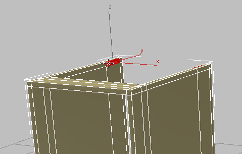
- Click (Bridge) again.
3ds Max creates the rear counter support.
- Click an empty area of the viewport to deselect the polygons from the previous step.
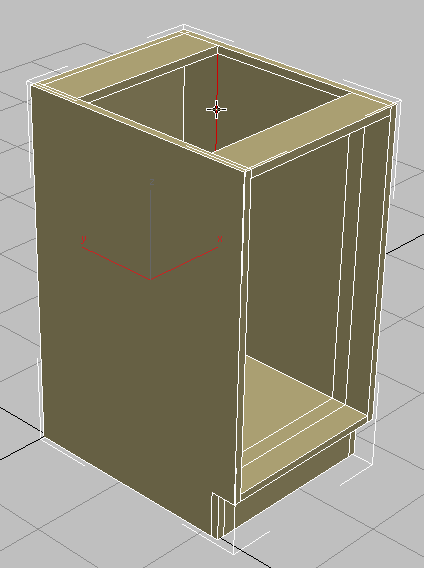
Create the back of the cabinet:
- Orbit,
 zoom, and
  pan the view so you can see the rear of the cabinet and the inside of the panel on the right.
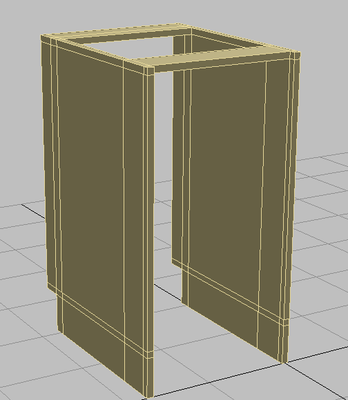
- On the ribbon Modify Selection panel drop-down portion, click
 (Step Mode) to activate it.
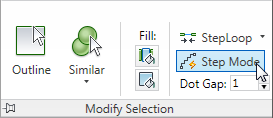
When Step mode is active, selecting two sub-objects (in this case, polygons) also selects the polygons along the shortest path between the two sub-objects.
- Click to select the inside top-left polygon at the back of the cabinet, then +click the inside bottom-left polygon.
- Orbit, then +click to select the corresponding vertical polygons on the opposite side of the back of the cabinet.

- Click (Bridge).
Back panel created from selected polygons
- Deselect the back cabinet board you just created, then orbit so you can see the front of the cabinet again (or press +Z a number of times to undo your view changes).
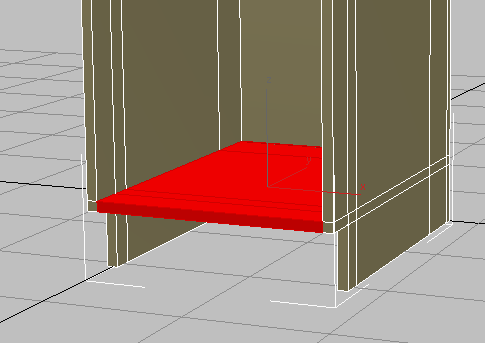
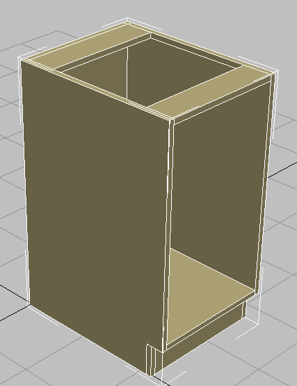
Create the bottom shelf and base board:
- Click to select the leading polygon at the bottom of the overhanging portion of the panel, as shown in the next illustration.
- Orbit, then +click to select the corresponding polygon on the other side of the cabinet.
3ds Max selects a loop of polygons that runs around the inside of the bottom of the cabinet.
- +click to deselect the polygon on the inside of the back cabinet board.
- Click (Bridge).
3ds Max creates the bottom shelf.
The only task that remains to complete the cabinet body is the base board or “kick plate.”
- Click
 (Step Mode) again to deactivate it.
 - Click and +click to select the left and right polygons at the base of the cabinet.
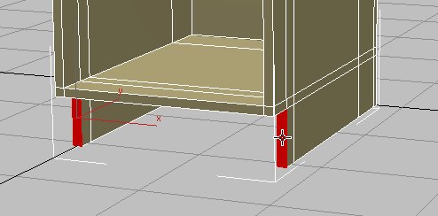
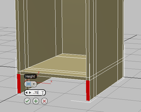
- On the ribbon Polygons panel, +click (Extrude).
- On the second caddy control for the Extrude tool, Height, set the value to 0.75 and then click (OK).
- Click an empty area of the viewport to deselect all polygons.
- Orbit so you can see the inner faces at the bottom of the cabinet.
- Click and +click the inside faces of the left and right polygon extrusions you just created.
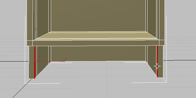
- On the ribbon Polygons panel, click (Bridge).
Next, you will remove a number of edges that, while important to this point for polygon creation, are no longer needed.
Remove excess edges:
- On the ViewCube, click the Home icon, then zoom and pan so you have a good perspective view of the cabinet.
- On the ribbon Polygon Modeling panel, click to activate (Edge).
- On the Modify Selection panel, click to activate
 (Loop Mode).
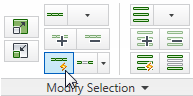
Any edge you now select, will also select all the other edges in the loop it is part of.
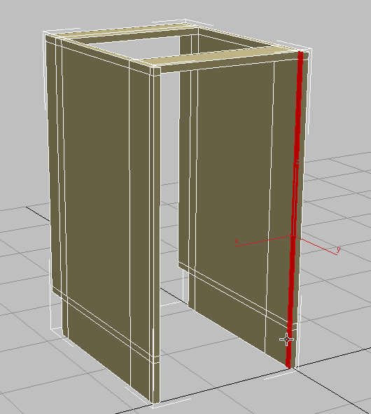
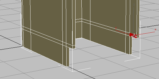
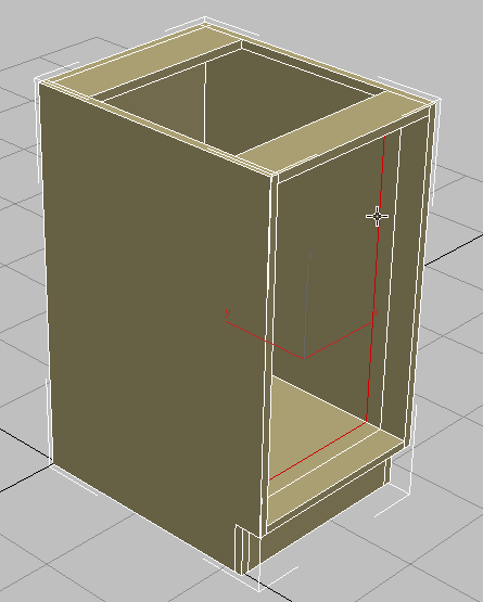
- Click the edge shown in the next illustration.

- On the ribbon Loops panel, +click
 (Remove Loop).
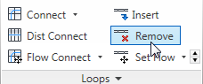
By
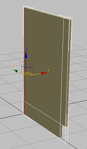
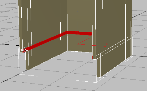
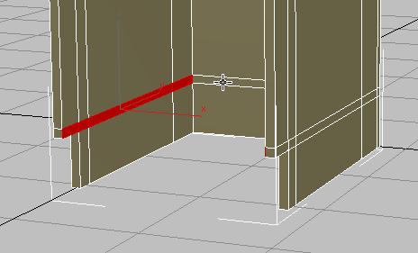
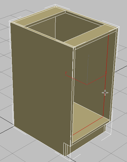
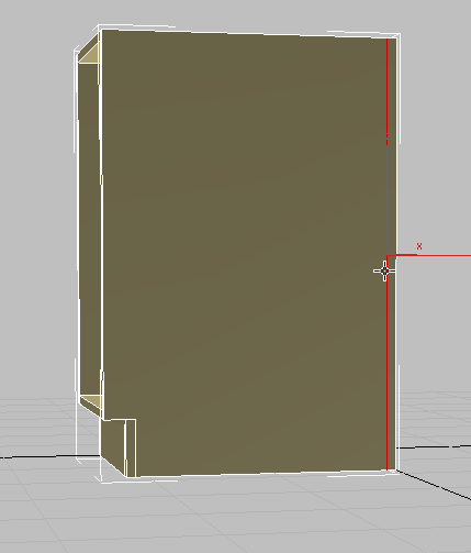
+clicking, you are removing both the loop, and any vertices created by the loop. - Continue to select edge loops on the side of the cabinet and +click (Remove Loop) until the side panel appears to be a single piece of wood again, as shown in the next illustration.
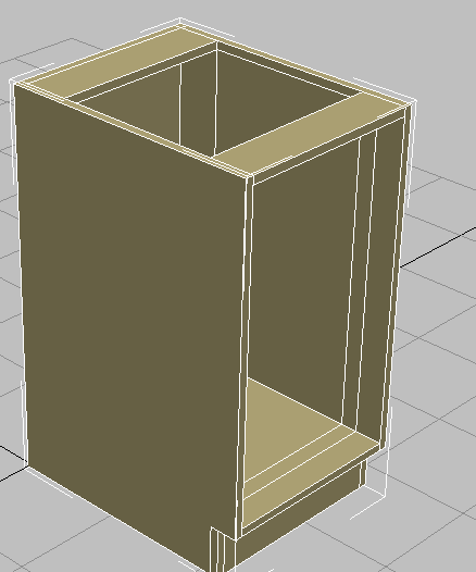
Left side of cabinet with all extra edges removed
- Using the same technique, remove the edge loops on the inside of the other panel of the cabinet.
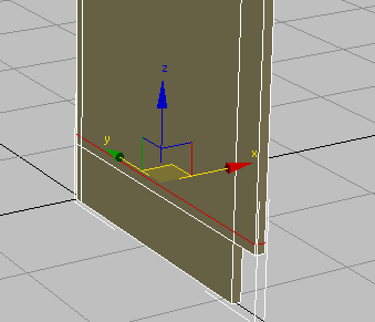
- Click and +click the edges on each side of the kick plate, then +click (Remove Loop).
- Orbit the cabinet to see its opposite side, then select and delete the loop toward the back of the board.
- On the ribbon Polygon Modeling panel, click (Edge) to exit the Edge sub-object mode.
Reposition the pivot point:
- Go to the Hierarchy panel, and in the Adjust Pivot rollout Move/Rotate/Scale group, click Affect Pivot Only to turn it on.
- On the main toolbar, click
 (Align), then in the viewport, click the cabinet.
 - In the Align Selection dialog Align Position (World) group, make sure X Position is on and Y Position and Z Position are off. In the Current Object group, choose Pivot Point and in the Target Object group, choose Center, then click OK.
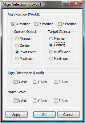
- Click Affect Pivot Only again to exit pivot-translation mode.
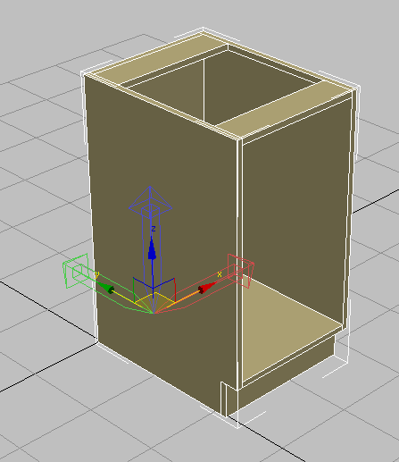
- With
 Move active, in the status bar transform fields, right-click the X spinner arrows to move the cabinet back to the world origin coordinates (0,0,0).
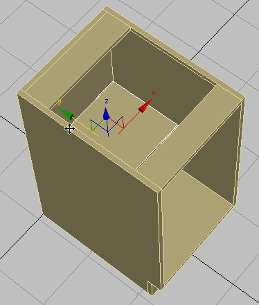
Now you will move the pivot point from its current position at the bottom-left corner of the cabinet to the bottom midpoint of its backboard. By doing this, you will make it easier to attach the cabinet to its required position in a scene.
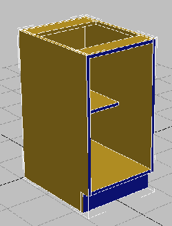
Create a shelf:
- On the Create panel, activate (Geometry), then on the Object Type rollout, click to activate Box.
- In the viewport, drag out a box of any size.
- In the Parameters rollout, set Length to 12.0, which will be the depth of the shelf. Set Width to 16 3/8, and Height to 0.75, which is the thickness of the cabinet boards.
The Width is based on the full width of the cabinet (18 inches), less the 3/4 inch width of each side board, less another 1/8 inch space to provide room to remove the shelf, if needed.
- On the main toolbar, click (Align), then in the viewport, click the cabinet.
- In the Align Selection dialog Align Position (World) group, turn on X Position, Y Position, and Z Position. In the Current Object and Target Object groups, choose Center, then click OK.
- On the main toolbar, click (Select And Move), then move the shelf on its Y axis until it is touching the backboard.
- Select the cabinet.
- On the ribbon Polygon Modeling panel, click Modify Mode.
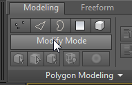
When active, Modify Mode makes the entire array of Graphite Modeling Tools available.
- On the Geometry panel, click (Attach), then in the viewport, click the shelf.
This makes the shelf and the cabinet both part of a single object.
Assign material IDs:
- On the main toolbar, click
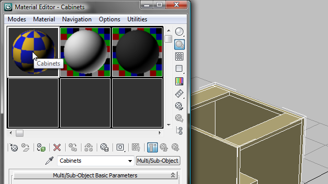
 (Material Editor) to open the Compact Material Editor. Note: There are two versions of the Material Editor: the Compact interface, and the Slate interface. The Slate version is more versatile when you are designing materials, while the Compact version is a bit more convenient when you just need to assign existing materials.
 - Click the top-left sample slot to make it active. The material in this slot is named Cabinets.
- In the Material Editor, click
 (Assign Material To Selection).
 -
 Close the Compact Material Editor.
 - On the ribbon Polygon Modeling panel, activate (Polygon).
- Press +A to select all the polygons in the cabinet.
- On the ribbon Properties panel drop-down portion, click
 (MatIDs).
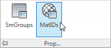
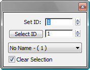
3ds Max opens a Set ID dialog.
- On the Set ID dialog, type 1 in the Set ID field, then press .
-
 Close the Set ID dialog.
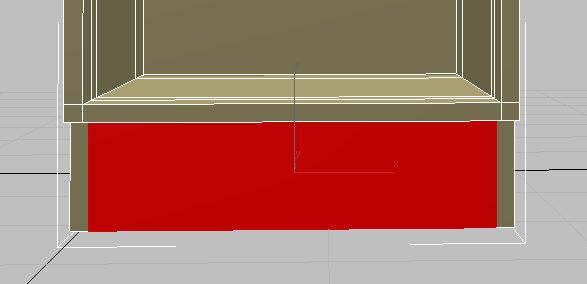
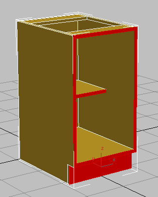
 - Click an empty part of the viewport to deselect all polygons, then click and +click to select the polygons that face forward, as shown in the next illustration.
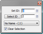
- On the ribbon Properties panel drop-down portion, click (MatIDs) once more.
- On the Set ID dialog, type 2 in the Set ID field, then press .
- Close the Set ID dialog.
- Click an empty part of the viewport to deselect the polygons.
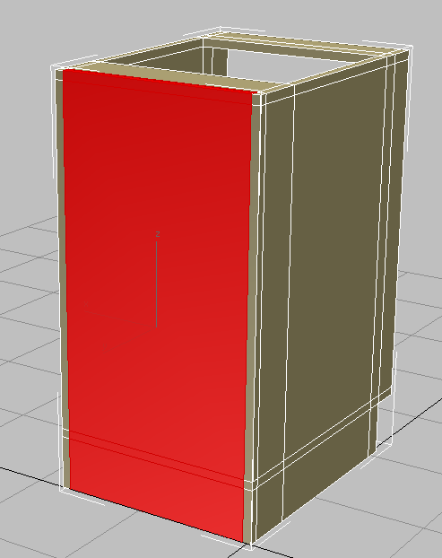
The front faces of the cabinet change color. They are assigned a different material ID number than the rest of the cabinet, and so they receive a different sub-material.
- On the ribbon Polygon Modeling panel, click
 (Polygon) to exit the Polygon sub-object level.
Now you will assign material IDs to the cabinet polygons so they can receive different types of materials.