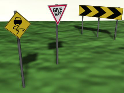
Sign objects represent road signs and road-marking symbols.

Sign objects in Civil View are created using one of two parametric sign object plug-ins. The first of these creates traditional sign objects, while the second generates road-marking symbols such as direction arrows and warning text.
Because all sign objects are parametric, attributes such as sign size, post height, and number of posts can be changed at any time.
The geometry of a sign face is always rectangular, but you can use an opacity map to model other sign shapes.
Civil View applies the CivilViewObjects material to all sign objects.
When you use the Object Placement Style Editor to place road signs, the objects are derived directly from the sign-face bitmap.
Object INI File Structure
|
Sign Object INI File |
|
[Parameters] Width= Height=
[Maps] Diffuse= Opacity=
[Sign Defaults] Style= Posts= GroundClearance=
[Group] Name=
|
[Parameters]
- Width / Height
-
Set the width and height of the sign face or road-marking symbol. The dimensions must be positive values.
[Maps]
- Diffuse
- Names the bitmap that defines the color and appearance of the sign face. This file must exist within the /matlibs/signmaps folder within any current Civil View resource kit.
- Opacity
- This bitmap (typically black and white) defines the shape of the resulting sign face at render time. Black areas of the bitmap are rendered as transparent portions of the object. This file must exist within the same /matlibs/signmaps folder as the main bitmap.
[Sign Defaults]
- Style
-
The type of parametric sign object required. This setting should be "1", "2", or "3" (no quotation marks are necessary):
- 1: A traditional sign that can have supporting posts.
- 2: A road-marking symbol.

Example of a road marking
Diffuse and opacity maps for road-marking symbols should normally be the same black and white bitmap file unless other road-marking colors are required. Black areas of the bitmap are not rendered.
Tip: When you create road-marking symbols, use the Object Placement Style Editor or Position Controller rollout to assign a parent surface so the road marking is correctly draped across the highway.The vertical offset of the road-marking object from the underlying ground surface is derived from the Vertical Shift value on the Scene Settings rollout, added to the Vertical Offset value on the Object Placement Style Editor. (Suggestion: Set the Vertical Offset value to 0.0 and use the Vertical Shift value only.)
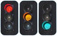
- 3: A dynamic traffic signal.
This is similar to option 1, a traditional sign, except that the bitmap contains multiple images. Only one of these images is visible at any time, so Civil View models a dynamic signal by animating the change between bitmap images.

Bitmap for a stop light
For more information, see Traffic Signal Parameters Rollout.
- Posts
- Sets the number of posts on which the sign face stands. Valid values are between 0 and 6. Use a value of 0 if the sign is to be placed above the highway on a gantry.
This value is ignored if the sign style is "2".
- GroundClearance
- The height of the sign plate above ground level. This value is the vertical distance between the underside of the sign plate and the ground.
This setting is ignored if the sign style is "2".
[Group]
- Name
- The name of the category sub-group in which this object should be listed. If no name is specified, the object will be listed as ungrouped.
Adding Custom Signs to the Library
To add a custom sign to the library, create a diffuse bitmap file and an opacity bitmap (if required), then add the bitmaps to the /matlibs/signmaps folder within the Civil View resource kit you want to use. Then create an associated INI file, in the format described above, and place it in the /objlibs/signs folder in the same Civil View resource kit. Multiple INI files can reference the same bitmaps.
Please also refer to the general instructions on object library customization in Civil View Object Library Overview.