Simulation Composite Analysis requires specific material parameters to predict the fatigue life of composite materials accurately.
Here we will cover creating a new material using Composite Material Manager and defining S-N data to be used in a progressive fatigue analysis. For more information on Composite Material Manager and the S-N data required for a fatigue analysis, you are directed to the Composite Material Manager User's Guide (Unidirectional Fatigue Tab and Woven Fatigue Tab). This tutorial requires the use of AS4-PEEK (a unidirectional material).
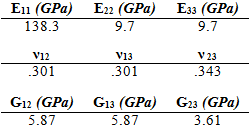
The material to be created is AS4_PEEK, with engineering constants defined in the table below and a fiber volume fraction of 0.61 [1].
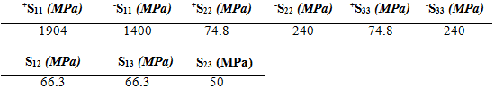
The strengths of the material are given in below [1].
The longitudinal S-N lamina test data is given below with a load ratio of 0.1 and a frequency of 10 Hz.
| S (Pa) | Cycles to Failure | Frequency (Hz) | Load Ratio | Angle (°) | |
|---|---|---|---|---|---|
| 1.655E+09 | 6.056E+01 | 10 | 0.1 | 0.0 | |
| 1.197E+09 | 1.741E+03 | 10 | 0.1 | 0.0 | |
| 1.407E+09 | 2.520E+03 | 10 | 0.1 | 0.0 | |
| 1.219E+09 | 8.930E+03 | 10 | 0.1 | 0.0 | |
| 1.134E+09 | 1.481E+04 | 10 | 0.1 | 0.0 | |
| 9.822E+08 | 1.995E+04 | 10 | 0.1 | 0.0 | |
| 8.977E+08 | 3.886E+05 | 10 | 0.1 | 0.0 | |
| 8.977E+08 | 5.882E+05 | 10 | 0.1 | 0.0 |
The transverse S-N lamina test data is given below with a load ration of 0.1 and a frequency of 10 Hz [1].
| S (Pa) | Cycles to Failure | Frequency (Hz) | Load Ratio | Angle (°) | |
|---|---|---|---|---|---|
| 3.247E+08 | 9.554E+02 | 10 | 0.1 | 10 | |
| 3.026E+08 | 1.614E+05 | 10 | 0.1 | 10 | |
| 2.772E+08 | 3.348E+05 | 10 | 0.1 | 10 | |
| 2.539E+08 | 1.982E+06 | 10 | 0.1 | 10 | |
| 1.170E+08 | 1.476E+03 | 10 | 0.1 | 30 | |
| 1.130E+08 | 6.203E+04 | 10 | 0.1 | 30 | |
| 1.000E+08 | 7.961E+05 | 10 | 0.1 | 30 | |
| 9.153E+07 | 2.122E+03 | 10 | 0.1 | 45 | |
| 8.679E+07 | 6.485E+04 | 10 | 0.1 | 45 | |
| 8.230E+07 | 4.821E+05 | 10 | 0.1 | 45 | |
| 7.943E+07 | 4.702E+04 | 10 | 0.1 | 60 | |
| 7.017E+07 | 1.143E+05 | 10 | 0.1 | 60 | |
| 7.017E+07 | 1.683E+05 | 10 | 0.1 | 60 | |
| 6.793E+07 | 4.384E+03 | 10 | 0.1 | 90 | |
| 6.113E+07 | 7.232E+04 | 10 | 0.1 | 90 | |
| 5.311E+07 | 1.399E+05 | 10 | 0.1 | 90 | |
| 4.951E+07 | 1.531E+06 | 10 | 0.1 | 90 |