We will create a boundary condition to impose a vertical displacement along the top surface of the coupon.
The coupon is loaded using displacements because it results in a more gradual failure process than a similar loading using applied forces. When a simple structure, such as this coupon, begins to fail under the action of applied forces, the structure fails rapidly because the load continues to increase as the load carrying capacity of the structure decreases. With a displacement controlled loading, the load carried by the structure decreases as the structure fails, which allows for a slower rate of failure.
First, we will apply an equation constraint to allow for simple determination of the total reaction force during post-processing.
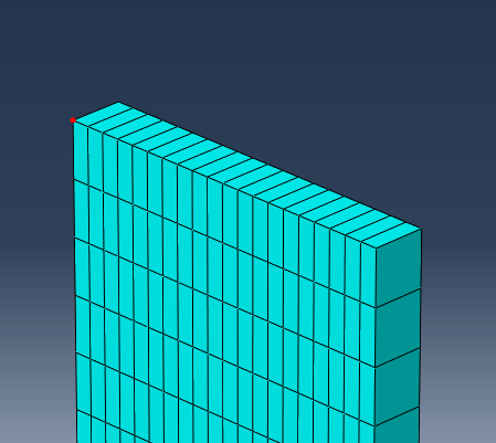
- Create a node set () named Load_Node. Select the node highlighted below.
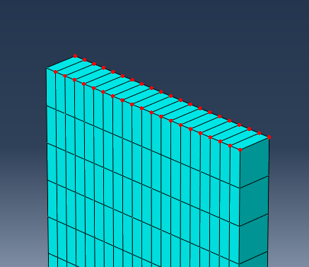
- Create a second node set named Tied_Nodes. Select the nodes highlighted below. Note: To quickly select these nodes, enable 'by angle' selection and select all nodes on the face, then switch back to 'individually' selection mode and deselect the Load_Node by clicking it while holding down the Ctrl button.
- Switch to the Interaction module.
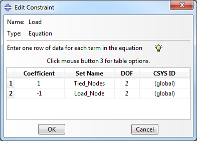
- To constrain the y-direction displacement of the tied nodes to the load node, select and select the Equation type. Name the constraint Load. Fill out the Edit Constraint dialog box so that it appears as shown below.
- In the Load module, create a Displacement/Rotation type boundary condition named Disp_Load in the Load_Step. When prompted to select a region, choose the Set option and select the Load_Node set. Enter 1.65 as the value for U2.