In the element definition dialog, you can define prefabricated, volumetric elements of complex geometry, such as spread footings and stairs.
There are 2 types of element definition:
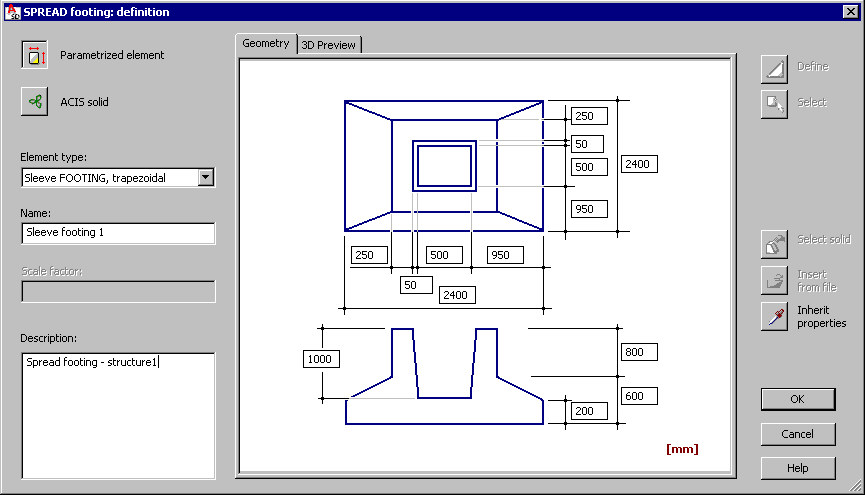
 Parametrized element - specify dimensions that define the geometry of a selected type of prefabricated element. A defined element is saved to the database.
 For spread footings, there are 2 icons on the right
 Define - use this to define a shape of the spread footing cross-section.
  Select - use this to define a shape of the spread footing cross-section by selecting a closed polyline (created using AutoCAD).
  ACIS solid - define a prefabricated element by defining or indicating an ACIS solid (an AutoCAD 3D solid or a group of objects (block) of the Face type).
 After you select ACIS solid, there are 2 icons on the right
 Select solid - use this to indicate an existing ACIS solid defined by means of the available AutoCAD options.
  Insert from file - use this to insert a solid from a DWG file (a DWG file may include a definition of only 1 solid).
 A defined element is saved to the database.
The Geometry tab displays a schematic drawing of a prefabricated element type and characteristic dimensions of the section. The 3D Preview tab includes a 3D drawing of a defined element.
Specify element parameters:
- Element type - the contents of this list depend on the type of prefabricated element for which the dialog has been opened
- Spread footings
- Prefabricated beams
- Prefabricated columns
- Stairs
- Slabs
- Walls
- Continuous footings
- Raft foundations
- Ground beams
- Name - specify the name of a defined element
- Scale factor - specify a value of the scale factor according to the AutoCAD rules
- Description - give an additional description of a defined element. This description will be provided in the INFO window (the Element info option).