Fillets create a transition surface between two surfaces or sets of surfaces.
Create a fillet surface between existing surfaces
- Choose Surfaces > Multi-Surface Fillet > Surface Fillet

 .
. - Set the construction type to Radius or Chord. (See the section Choose the type of a fillet surface for more information.)
- Check on Variable Fillets if you want the radius or chordal distance of the fillet to vary along its length.
- Select both sets of surfaces, by picking them individually or using a selection box. Note: When Alias detects a tangent break between surfaces, it automatically puts them in separate sets.
An arrow appears for each set of surfaces, indicating on which side of the surfaces the fillet will be built. The software makes an educated guess about where you intend to build the fillet, and orients the arrows accordingly.
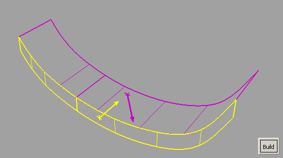
- Click on an arrow to flip its direction, or click on a surface to make the indicator appear at that location.
- Click Build.
The fillet is built on the side of the surfaces indicated by the arrows.
- For variable fillet surfaces, use the manipulators to control the radius (or chordal distance) along the length of the fillet. (See the sections Control the radius along the length of a variable fillet surface and Control the chordal length along a variable fillet surface for more information.)
- Use the options in the Surface Fillet Control window to control the shape of the fillet surface. (See the section Manipulate fillet surface cross section and continuity for more information.)
- When editing construction history, click surfaces to add them or remove them from the sets.
If Surface Type is set to Multiple surfaces and curves-on-surface are created at the edges of the fillets (see Trim Type option) those curves-on-surface are segmented to correspond to the multiple fillet surface boundaries. To create the curves-on-surface as a single piece (for each surface), set Surface Type to Single surface
Create a fillet surface between surface curves
Freeform blend lets you create a fillet between surface curves (surface boundaries, trim edges, Isoparametric curves or Curves-on-surface).
In other words, you use surface curves on the two sets of surfaces to define the contact lines at the ends of the fillet.
You can also select free curves. If a contact line is made up entirely of free curves, that side reverts to G0 Position continuity. As well, Edge align is not possible on that side. If a contact line is made up of both free curves and surface curves, then up to G1 Tangent continuity is allowed on that side. You can only attempt Edge align for the surface curve sections.
- Choose Surfaces > Multi-Surface Blend > Freeform Blend
 .
. - Click surface curves on the first set of surfaces to define the contact line.
The first set of curves is highlighted in purple.
Note:If Chain Pick is turned on in the option window, selecting the boundary of one surface will also select all other boundaries that are tangent continuous with it.
- Repeat for the second surface or set of surfaces.
The second set of curves is highlighted in yellow.
- Click the Update button.
(This is not necessary if Auto Update is turned on in the option window.)
Adjust the alignment of the edges of the fillet/blend surfaces
Use the options in the Flow Control section, or click the labels on the model, to control how the blend surface(s) edges (in the V direction) meet up with the edges of the boundary surfaces. You can adjust the alignment of the start, end, and (if more than one blend surface) interior edges.
See Surfaces > Multi-Surface Blend > Freeform Blend![]() ) for an explanation of the possible values.
) for an explanation of the possible values.
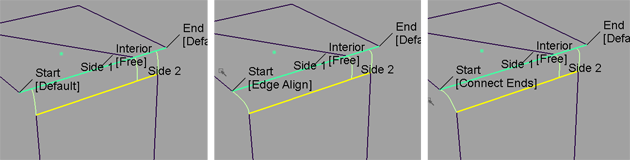
Possible flow control values for Start of blend
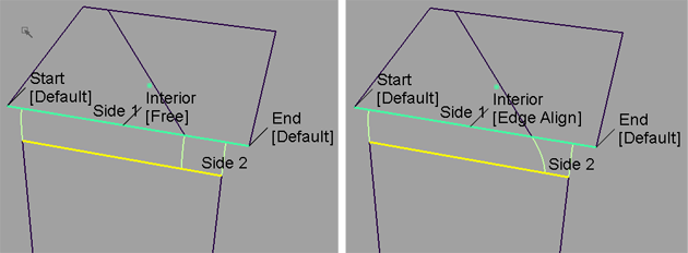
Possible flow control values for Interior of blend
What if...?
- The fillet surface will not build?
Try lowering the fillet radius. Often the fillet does not build simply because there is not enough room to create the radius set in the options.
- I don’t want to trim the surfaces back?
The default is to automatically trim the surfaces back to the new fillet surface. Use the Trim Type option in the control window to have the fillet tool only create curves-on-surface (but not trim), or turn trimming off completely.