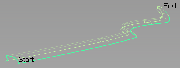
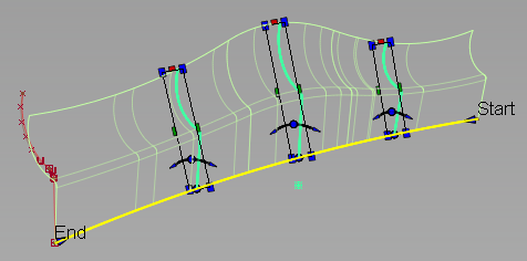
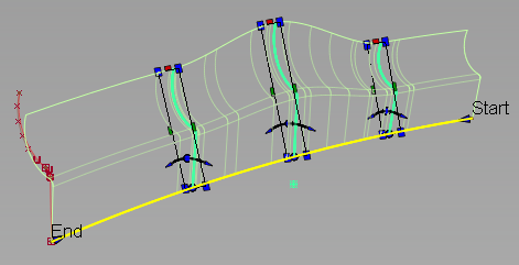
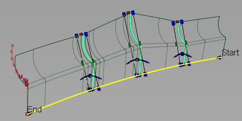
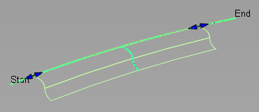
Creates a surface by sweeping one or more profiles along one or more path curves (rails). The profiles are maintained relative to the coordinate system, the path normal, or defined vectors.
Use Profile to create and modify extruded surfaces with maximum control over section transition and location.
A profile is composed of one or more planar curves. It can have sharp bends and can be closed.
If several profiles are used, they can have different shapes but must have a similar structure (segmentation between sharp bends or number of spans). Each profile can have an individual position and orientation relative to the rail curve. If the curves within a profile set are disconnected (not G0), it is best to create a separate profile surface for each element of the set.
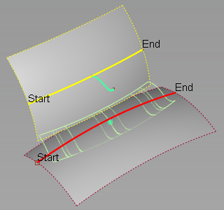
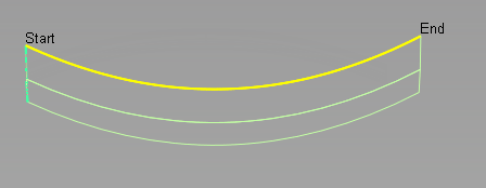
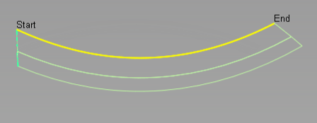
Rails can include curves and surface curves. Rails must be position and tangent continuous. They can be closed. You can use multiple tangent continuous rail curves with chain select or by making additional selections before accepting the rail input.
Profile Control options
- Profile Orientation
-
Natural – The orientation of the profile frame is determined only by the Frame Travel.
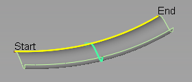
Natural Orientation, Parallel Frame Travel
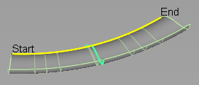
Natural Orientation, Radial Frame Travel
Rotate to Target – The profile rotates about the rail curve until it touches a selected Profile Target.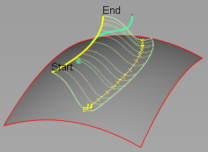
Rotate to Target Orientation, Surface Target, Radial Frame Travel
Rotate to Target Orientation, Curve Target, Radial Frame Travel
Slide to Target – The profile slides along an attached surface until it touches the selected Profile Target. The profile rotates so that the profile frame remains tangent to the sliding surface.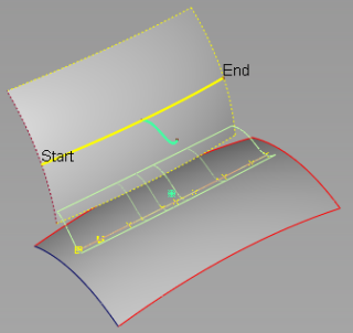
Slide to Target Orientation, Surface Target, Radial Travel
Slide to Target Orientation, Curve Target, Radial Travel
Guide Curve – The orientation of the profile frame is determined by the normal direction of an adjacent curve.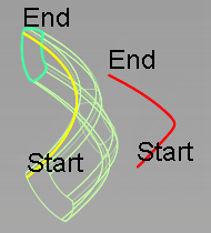
Guide Curve Orientation, 2D Scaling, Parallel Travel
Surface Normal – The orientation of the profile frame is determined by the normal direction of an adjacent surface at the closest point between the rail curve and the surface.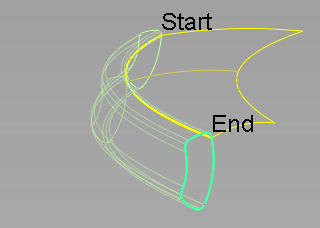
2nd Rail – The orientation of the profile is determined by connecting the profile curve to two rail curves.
- Profile Target
-
Surface Target – If Rotate to Target is selected, the profile rotates around the rail curve until it touches the target surface . If Slide to Target is selected, the profile "slides" along an attached surface until it touches the target surface.
If Use Profile Point is also selected, the profile rotates or slides until the selected point on the profile touches the surface.
- Curve Target – If Rotate to Target is selected, the profile rotates around the rail curve until it touches a selected curve. If Slide to Target is selected, the profile "slides" along an attached surface until it touches the target curve.
If Use Profile Point is also selected, the profile rotates or slides until the selected point on the profile touches the curve.
- Use Profile Point
-
If Use Profile Point is also selected, the profile rotates or slides until the selected point on the profile touches the surface or curve.
If Rotate to Target or Slide to Target are selected, enables you to select the point on the profile that will touch the target. - Profile Scaling
-
Scales the profile with the influence of the target curve.
No Scaling – Does not scale the profile.
Non-proportional Scaling – Scales the profile non-proportionally in one direction.
Proportional Scaling – Scales the profile proportionally in two dimesions of the local coordinate system.
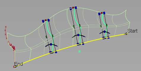
- Frame Travel
-
The profile frame is the coordinate system used to define the profile section orientation and transformations along the path.
Select how the profile frame travels or sweeps along the path.
Parallel – The profile frame is set to travel parallel to profile plane.
Radial – The profile frame pivots to maintain the same angle relative to the rail curve normal.
- Transition type
-
This option specifies the type of blend between multiple profiles (either from input curves, or manipulators). It determines the shape of the surface isoparms that run in the direction of the rail curve.
Global – Provides a smoother overall shape, but sometimes leads to excessive undulations.
Global – Provides a smoother overall shape, but sometimes leads to excessive undulations.
Local – Provides smooth transitions around the locations of the profiles.
Limited – Attempts to control the shape of the surface so that it stays within the range of the profile scales. This setting avoids the over and under shooting that sometimes occur with Global or Local transition type.
Linear – Joins the profiles with straight lines.
Explicit Control Options
- (Length) U Degree
-
Degree of the profile surface in the U direction (along the rail curve).
- (Section) V Degree
-
Degree of the profile surface in the V direction (along the profile section).
- Maximum Spans
-
If Surface Type is set to Multiple Surfaces, this value specifies the maximum number of spans for each surface in profile surface group.
- Transition type
- Explicit Control
-
Select this option to display control options which allow you to explicitly specify the degree and number of spans of the profile surface in both the U and V direction.
- Match Parameterization
-
Select this option to use the input geometry for the profile parameterization.
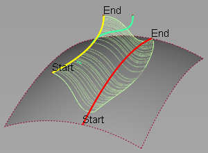
Modify Range
- Modify Range
-
Select this option to define a portion of each rail as input for the profile surface using range manipulators, or using the Start and End sliders.
Setting the Start and End sliders to 0.0 and 1.0 resets the original extent.
Surface Structure
- Surface Type
-
Multiple Surfaces – A separate surface is created for each of the profile curves you selected, and the surfaces are grouped.
Single Surface – A single surface is built.
- Bezier Surfaces
-
This option only appears if Surface Type is set to Multiple Surfaces. If it is selected, each surface will be a Bézier patch.
Bézier patches have a single span, and their maximum degree in the U direction is set through the Explicit Control section. The default is the degree of the rail curve.
- Short Edge Tolerance
-
To prevent adding spans that are too close to each other, the system will not allow spans of a linear distance less than the Short Edge Tolerance.
Control Options
- Auto Update
- Updates the new surface automatically as you change the values in the Profile Control window.
- Chain Select
-
If this option is selected, selecting a surface curve also selects all other surface curves that are tangent continuous with it.
- Deviation Check
- Displays the deviation between the created profile surface and theoretical perfect result.